

Installation
What are the steps for installation?
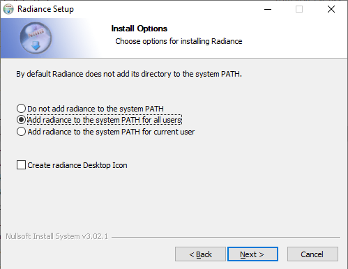
- Right-Click the MBSDaylightForRevitSetup.exe file and Select Run as administrator. This ensures future software updates can be obtained without admin privileges.
- It installs .Net framework and Radiance dependencies along with the MBS Daylight for Revit DLL and settings files.
- Remember to Select Add radiance to the system PATH for all users.
What are the steps for updating the software?
- Software Update dialog will automatically open on the first run after the installation.
- For future updates, follow the below steps
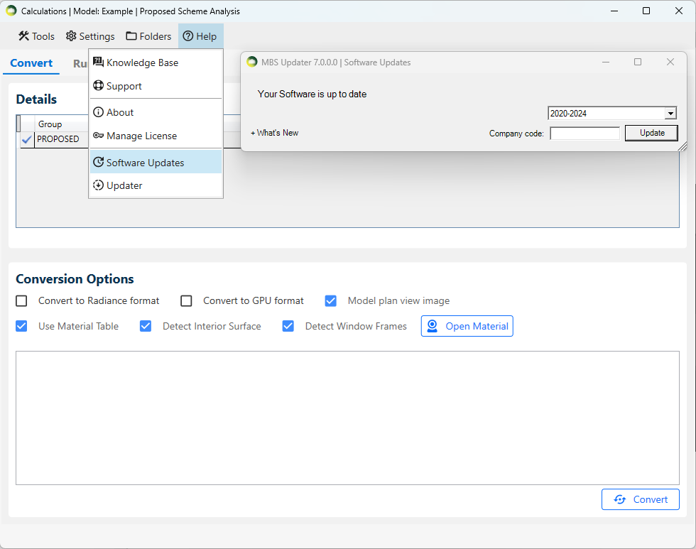
- Open the MBSCalculation dialog > Help > Software Updates > Update
- Revit and any MBS Calculation service consoles must be restarted after the update.
- What’s New expander can be clicked to check the list of the latest changes.
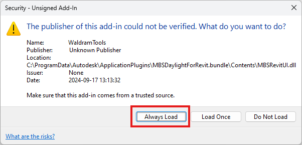
How to avoid security warning when opening revit?
- To suppress the security warning, please make sure you have clicked on Always Load button.
Licensing
How to activate the Trial License?
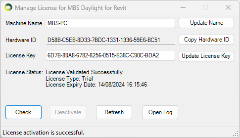
The Trial license is automatically activated when any of the MBS dialog is open for the first time.
- The license will be valid for 7 days from the time of activation and gives access to Full features of the Plugin.
To Check the status of the Trial License
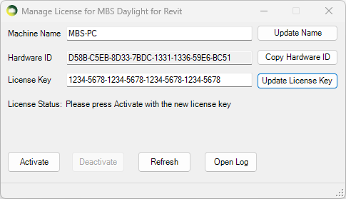
- Open MBS Calculation Dialog then Click on Help Menu > Manage License
- Press Check
How to upgrade to the Subscription License?
- Once you purchase a Subscription license from MBS, We will provide you with a Subscription version License key.
- Open MBS Calculation Dialog then Click on Help Menu > Manage License
- Paste the new key to the License Key textbox and Press Update.
- Press Activate. (Internet connection is required).
- The software validates the license regularly with our license server to allow the license to be used on multiple computers.
- Sometimes the firewall or anti-virus restrictions can block the license activation and validation. Contact us for details about the license server address which the IT team might need in order to allow the activation.
* The plugin can be installed and used on multiple computers. There is a 30 min cooling off period once the plugin is used on one computer before it can be used on another computer.
How to transfer the software license to another computer?
- The plugin can be installed and used on multiple computers.
- There is a 30 min cooling off period once the plugin is used on one computer before it can be used on another computer.
- If the plugin needs to be used before the cooling off period, the license needs to be de-activated from the computer where it was last used.
- Open MBS Calculations Dialog then Click on Help Menu > Manage License.
- Press Deactivate
- Once it is de-activated, it can be used immediately on another computer.
Groups
Creating Groups
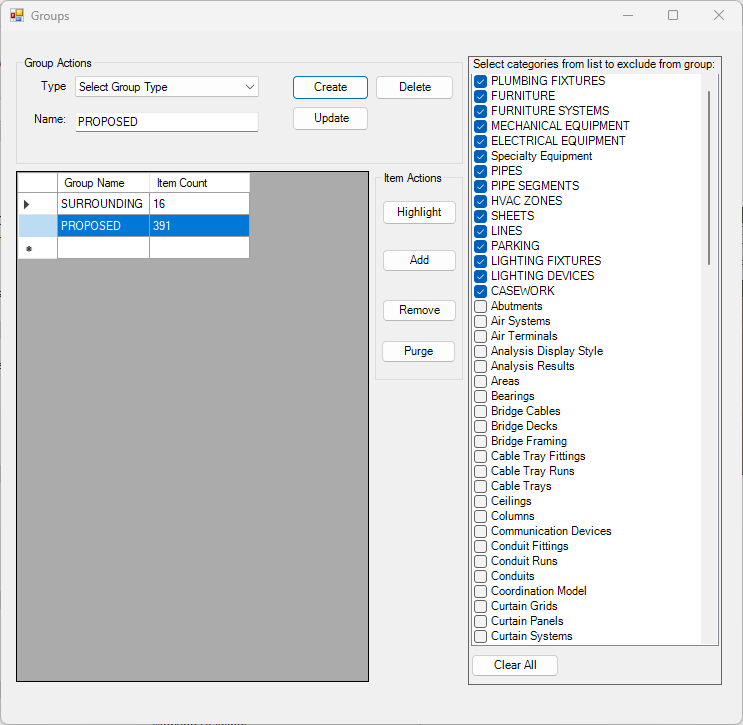
- Groups can be created by selecting from pre-populated common groups from the Type combo box or by selecting New Group, New Room Group, New Window Group option.
- Once the name is selected or input on the Name text box, Create button should be pressed which offers to select items to be added to the new group.
- Any item under a category which is ticked on the exclude list is ignored when selecting items to be added to the group.
- Some categories such as Plumbing and Furniture are always excluded from the groups by default.
- If those items need to be added to a group, they should be unticked from the exclude list temporarily.
- Room or Window group automatically filters only registered room/window when adding items.
Updating Groups
- Remove items under certain category
- Tick the categories on the exclude list and then Select the Group name and then Update button.
- Any objects under the newly ticked exclude categories will be removed from the group.
- Remove items by selecting them
- In order to remove items, press Remove button and then select the items to be removed from the group.
- In order to remove items by selection, the category which a item belongs to must not be ticked on the exclude list.
- Add new items to the group
- To add items by selection: Press Add button and select elements from the model to be added to the group.
- In order to add items under a category: Untick the category on the exclude list first, and then press Add button to select elements.
(unticking a category from the filter list would not automatically add category elements to the group.)
FAQs
How to exclude objects from Revit Links?
- Revit Links are inserted as single object to the group so it is not possible to exclude objects when adding them to the group.
- Objects from all phases are included and is not possible to filter by phase.
- They are filtered at the conversion time based on the exclusion list.
- Tick the categories on the exclude list and then close the group dialogue. The list is saved on Project settings and will be used on conversion time.
How to exclude objects from Imported Autocad DWG instances?
- Autocad DWG Links are inserted as single object to the group so it is not possible to exclude objects when adding them to the group.
- However it is possible to exclude objects by layer from the import instance itself.
- Select the imported dwg instance and then Click Modify and the Delete Layers. Select the layers to exclude and Press Ok.
- Refer to Revit help topic “Delete Layers in CAD files” for step by step guide.
Which groups should the windows be on?
- Windows must be added to the group where they exist.
- Windows on Proposed buildings should be added to Proposed group.
- Windows on Surrounding building should be added to Surrounding group.
- Any windows on Existing buildings should be added to Existing group.
- If Windows are registered after the model is converted, the model must be converted again to make sure the calculation process includes the windows correctly.
- The results will be incorrect if the registered Windows are not added to the relevant groups.
Setting up Linked model
How to setup linked model for registration?
Before starting the actual registration, we need to follow the below steps to setup the model.
It is recommended to check the below points by opening the linked model on it own:
-
- Assign the room use of the Rooms by using the Name property. They cannot be updated from the current Host model.
- Rooms and Windows can be registered to test if there is any issue with registration or Room-Window attachment. Although the registration is not carried to the Host model, Please remember to unregister them before linking to the Host model.
Once the model is linked to the Host model:
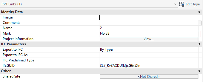
- Assign Mark for each linked instance which will be used as Building name when registering the rooms and windows from that instance.
- Select the link instance > Right-click on it.
- Click on the properties option.
- On the Properties palette, Assign the Mark. (See the image on right.)
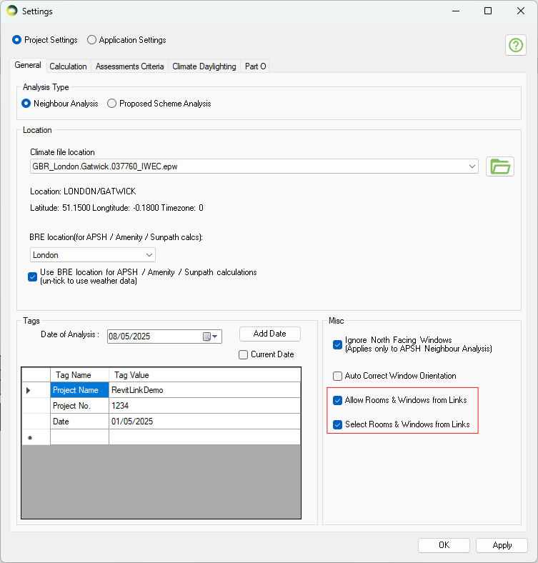
- Enable Rooms and Windows detection and selection options from settings.
- Open the MBS setting dialog.
- Then go to Project settings > General Tab.
- Tick the Allow Rooms & Windows from Links and Select Rooms & Windows from Links options.
- After these setups, you can register Windows and Rooms as usual.
For Details on registration in Revit follow this link.
Known Limitations
- The Room and Window name and result cannot be shown using Revit Tag objects. They are shown using Revit Text objects instead.
- The Linked model doesn’t store any registration or result information. All these information are stored in the Host model. So if the Linked model is linked to a new host model after registration, there will be No registration or result information. The information can also be lost if the linked model is Removed from the Manage Links dialog. Unload and Reload From will preserve the information.
How do I create plan view for linked model?
When the linked instances are in different elevations, the result might not be visible in default levels. In that case, you might be interested in creating your custom plan view, for this, there is an option to do so in MBS Daylight for Revit Software. Please follow the following instructions.
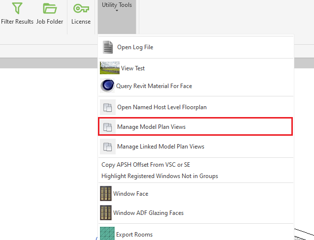
- Go to MBS Daylight for Revit option on the Revit Ribbon menu.
- Under Utility Tools click on the Manage Linked Model Plan View option.
- This will open up the new dialogue box.
- On the dialogue box, ensure you have provided the correct data such as FloorPlan Template, Tolerance and Prefix.
- Next, click on Select revit links.
- Once you select the links, it will display the levels to be created that match the Tolerance. For tolerance, link instances are compared against the lowest elevation among the selected links.
- Next, click on the Create Floor Plan button.
Registration
What are the steps to register Revit windows?
- Standard Revit Windows, Doors and Curtain panels with transparent glazing can be registered as windows. Windows modelled as Generic models can also be registered if they have faces with transparent glazing.
- Open the Register Dialog and go to Window tab.
- Detect All Windows button shows all the windows which can be registered.
- Users can also pick windows to register by using Select Manually button. Any windows which are already registered will not show up here.
- Press Register Window(s) button to register the windows which are selected on the data grid.
- Window Id
- Building Name is read from the Building combo box.
- Floor Name is read from the Revit Level where the window is placed. If Revit Level is not defined then the centre of the window is used to detect the correct level name.
- Window name is read from the Revit Parameter ‘Mark‘. If the Mark is empty, Prefix W will be used with a counter. e.g. W1 for the first unnamed window.
- Window Normal
- Normal is taken from the Window, Door object’s facing orientation.
- Normal is taken from the host wall’s facing orientation in case of Curtain panels.
- The Normal should be facing away from the room.
- If the orientation is incorrect for the windows, Auto Correct Window Orientation option can be used to obtain correct normal.
- The normal is decided by intersecting with room or floor in the direction of window facing orientation then on the opposite direction.
- It handles the situation when window/wall flipped are incorrectly.
- If there is no room and floor then window’s facing orientation will be used.
- Shared parameters
- Some of the window properties are added as shared parameters in the model and they can be updated via Window tags or schedule.
- Building name, description, property type, glazing transmittance, adf, vsc and apsh offset values can be updated.
What are the steps to register Revit Rooms?
- Standard Revit Rooms which are placed in the model and are correctly bounded by the walls can be registered as rooms.
- Open the Register Dialog and go to Room tab.
- Detect All Rooms button shows all the rooms which can be registered.
- Users can also pick rooms to register by using Select Manually button. Any rooms which are already registered will not show up here.
- Register Room(s) button registers the rooms which are selected on the data grid.
- Room Id
- Building Name is read from the Building combo box.
- Floor name is read from the Revit Level where the room is placed.
- Room name is read from the Revit Parameter ‘Number‘. If the Number field is empty, prefix R will be used with a counter. e.g. R1 for the first unnamed Room.
- Room type is read from the Revit Parameter ‘Name‘.
- Ceiling Height is set at time of registration based on ray intersection of the nearest ceiling or roof. If this method fails then value defined in the register dialog is used. It can be changed later by simply modifying the shared parameter property MBS_CeilingHeight on Revit room or by Updating it via the Ceiling Height text box in the Update Mode.
- Shared parameters
- Some of the room properties are added as shared parameters in the model and they can be updated via Room tags or schedule.
- Building name, description, property type, required adf value, adf reflectance values, ceiling height and grid spacing can be updated.
What are the steps to register Revit Amenities?
- Standard Revit Floor and Mass objects which are placed in the model can be registered as amenities.
- Floor objects can have multiple faces but each face must be planar. Non planar face results are not calculated/displayed correctly.
- Open the Register Dialog and go to Amenity tab.
- Detect All button shows all the amenities that matches Mark with keyword (e.g., Garden) listed in Marks For Detect All options.
- Users can also pick any Floor and Mass as amenities to register by using Select Manually button. It ignores the keyword check listed in Marks For Detect All options.
- Any amenities which are already registered will not show up here.
- Register button registers the amenities which are selected on the data grid.
- Amenity Id
- Building Name is read from the Building combo box.
- In case of linked model, the building name is taken from Mark of the linked instance.
- Floor name is read from the Revit Level where the amenity is placed.
- Amenity name is taken from Mark.
How to specify offset values for VSC, APSH, SE and ADF?
- The reference point for specifying the offset is on the glazing itself.
- Offset value should be positive to go towards the room and negative to go away from the room.
- The VSC offset will be set on the outside face of the window’s host wall.
- The APSH/SE offset will be set on the inside face of the window’s host wall.
- The ADF offset will be set in the middle of the window’s host wall.
- The offset values will be set 0 i.e. on the glazing itself if the host doesn’t define it’s width e.g. some curtain panel grids.
Can room/window groups be automatically created?
- RG_ALL and WG_ALL are created automatically once you close the register dialog after registering the relevent entities i.e. room or window.
- It is not necessary to add room or window manually to RG_ALL or WG_ALL group each time you register. These groups are updated on fly with all entities (room or window) when running calculation.
- Similarly, there are options to create or clear the groups for each entity type in modify dialog. For this follow the following steps:
- Open modfiy dialog from the menu.
- Click on relevent tab i.e. Window / Room
- Then click on
 icon.
icon.
- Also, the group can be manipulated from group dialogue in an organized way. For detailed instruction on group management, see Revit Group Instruction page.
Material Settings
About Material Dialogue
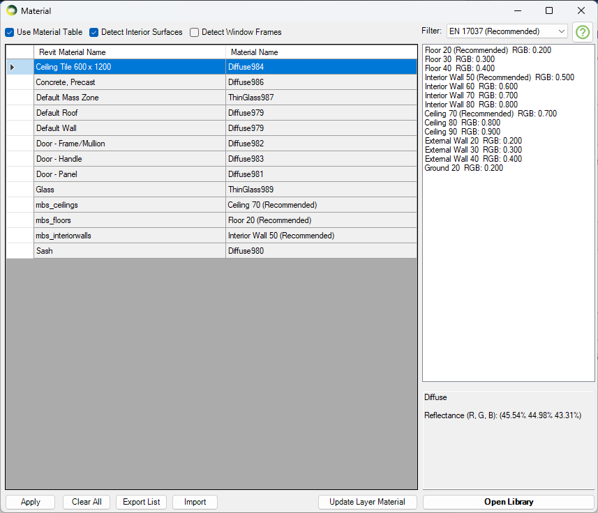
Material Dialogue can be opened by clicking on the material dialog icon on the tool bar or by clicking the Tools Menu then Materials. Using of the Material Table requires enabling the option by ticking the Use Material Table box on the Materials Dialogue.
– Using Material Table Mode
The material table is empty for a new project. The list is populated with the materials based on the face material in Revit. It can then be modified WITHOUT a need to re-convert the model. Therefore this gives more flexibility on experimenting different materials and parameters for an analysis.
Default diffuse material with reflectance read from layer colour (r = 51, g = 51, b = 51 translates to 0.279, 0.279, 0.279) is used for objects on that layer. RGB gamma correction is applied in order to make the rendered image look similar to when viewed in a Monitor.
Clearing the material list and Importing the material list from another project requires model reconversion. This is also the case on making any change to the model, like adding deleting objects or changes to the object layer.
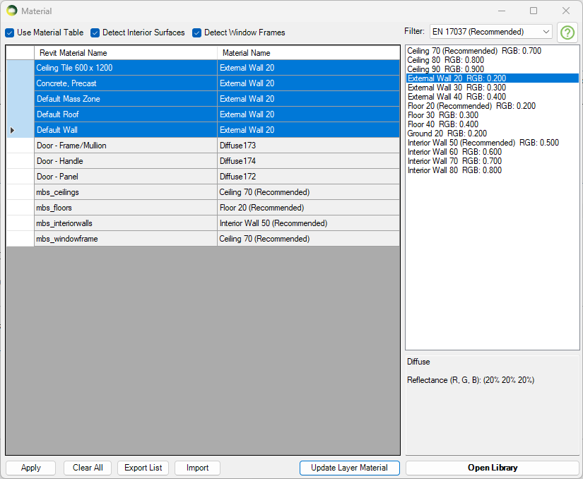
– Detecting Interior Surfaces
- The internal walls, ceiling and floors of all Revit Rooms (either MBS registered or not) can be detected.
- Tick the Detect Interior Surfaces option before converting the model.
- Special entries namely MBS_InteriorWalls, MBS_Floors, MBS_Ceilings and MBS_WindowFrame are added to the material table. So that they can be easily given relevent reflectance values without having to know the face material names applied to them in Revit.
– Not Using Material Table Mode
Default diffuse material with reflectance read from layer colour (r = 51, g = 51, b = 51 translates to 0.279, 0.279, 0.279) is used for objects on that layer.
Updating Material
Updating the Material for an entry
- Select one or more rows from the layer – material list on the left hand side for which you want to update the material.
- Select the desired material from the Material list on the right hand side and press Edit Material for Selected items.
- Press Update Layer Material.
- Repeat steps 1 – 3 as necessary for the layers.
- Press Apply and Close the dialog.
- Updating the materials this way doesn’t require model reconversion
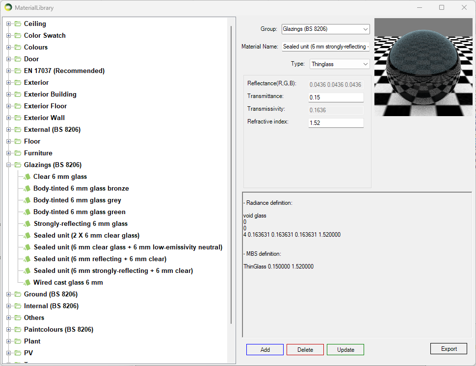
Adding New Material
Adding New Material to the library
- Click on the Open Library button
- Select a existing Group or Type a new group name for the material on the Group combo box.
- Type a unique name on the material name text box.
- Select a Material Type from the Type combo box. See below for detail on types.
- Assign material properties on the relevant text boxes.
- Press Add and Close this dialogue.
- Remember to Press Apply on the Material dialogue.
- Diffuse surface reflects light uniformly over the entire reflecting hemisphere. A Lambertian (or diffuse) surface appears equally bright from all viewing directions.
The reflectance parameter represents the fraction of the incident energy that is reflected at a surface. The parameter has three components which range from 0 to 1. - Mirror (specular reflection) surface only reflects light in one specific direction.
- ThinGlass is a special case of dielectric, infinitely thin and therefore does not change the transmitted ray direction. It is modelled as a single surface. The default refractive index is 1.52.
Transmittance is the ratio of the total transmitted light to the incident light which includes multiple inter-reflections in a layer of glass.
The parameter is a single value from 0 to 1 – Reflectance field is disabled as it is a function of angle, refractive index of the material and transmissivity.
Transmissivity applies to a single pass of light through a layer of glass and excludes multiple interreflections within the medium.
ThinGlass is translated to Radiance glass material. Transmittance value is converted to transmissivity for the Radiance rad file. - TransTree is a mix of Diffuse Reflection (representing leaves) and Specular Transmission(the gaps). See How to assign the Materials for Trees? for more details.
- Translucent material is a mix of diffuse reflectance/transmittance and perfect/glossy specular reflectance and transmittance. It describes diffuse and glossy specular reflection and transmission through the surface.
Translucent parameters are well described in this link: http://www.schorsch.com/en/software/rayfront/manual/transdef.html - BSDFRadiance material, only valid on Radiance method, is to define material for complex glazing system.
The input is an xml file containing BSDF matrix data. This file can be generated using WINDOW 6.0 BERKELEY LAB application.
Please follow instruction on BSDF Files for Radiance Renderings page.
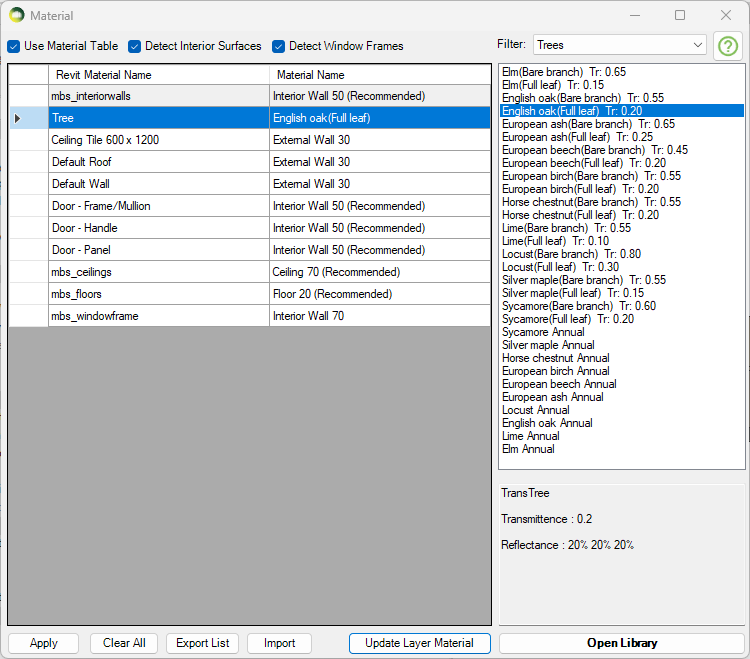
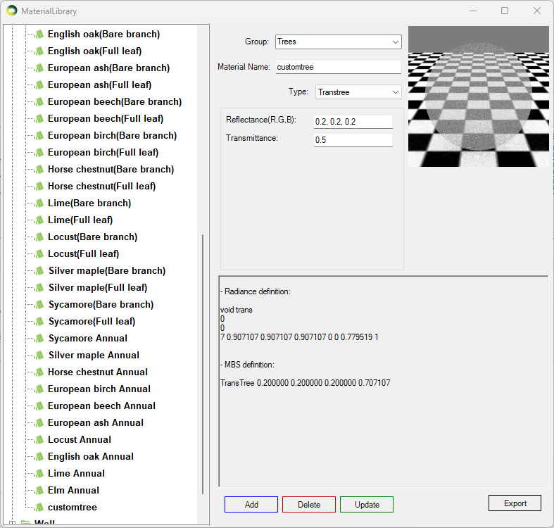
How to assign the Material for Trees?
Assign Tree Material from pre-defined BRE trees
TransTree is a mix of Diffuse Reflection (representing leaves) and Specular Transmission (the gaps). This material is suitable for simulating trees on BRE (VSC and ADF) or Daylight Factor calculations. The Reflectance value on VSC and ADF calculations only reflects in terms of the colour as no reflected light is accounted for. The Transmittance value is the overall transparency of tree crown as the ray enters and exists the tree volume. Follow the below steps to assign tree material to a layer:
- Put the tree objects with the same transparency to a layer.
- Then Open the Materials dialogue and assign one of the predefined BRE tree materials.
- The trees mentioned BRE Site Layout for Daylight & Sunlight Appendix H Table H1 are included in the material library.
*For Sunlight calculations, they should be run with opaque trees and without trees if necessary
(BRE Site Layout for Daylight & Sunlight Appendix G3)
*For SDA calculations please refer to https://www.mbs-software-uk.com/knowledge/sda-calculation-with-trees/
Creating a custom Tree material
- Open Material dialogue then Press Open Library button
- Create a new TransTree type material
- The reflectance values are used during DF calculation only. It is used for the colour of the tree in case of VSC and ADF calculations.
- The transmittance is converted automatically to consider the overall transparency of the tree crown as the ray enters and exits the tree volume.
- For example 50% overall transparency should be input as 0.5 which will then be converted to 0.707 (√0.5) to adjust for the ray entering and leaving the tree crown. This can also be seen on material preview area.
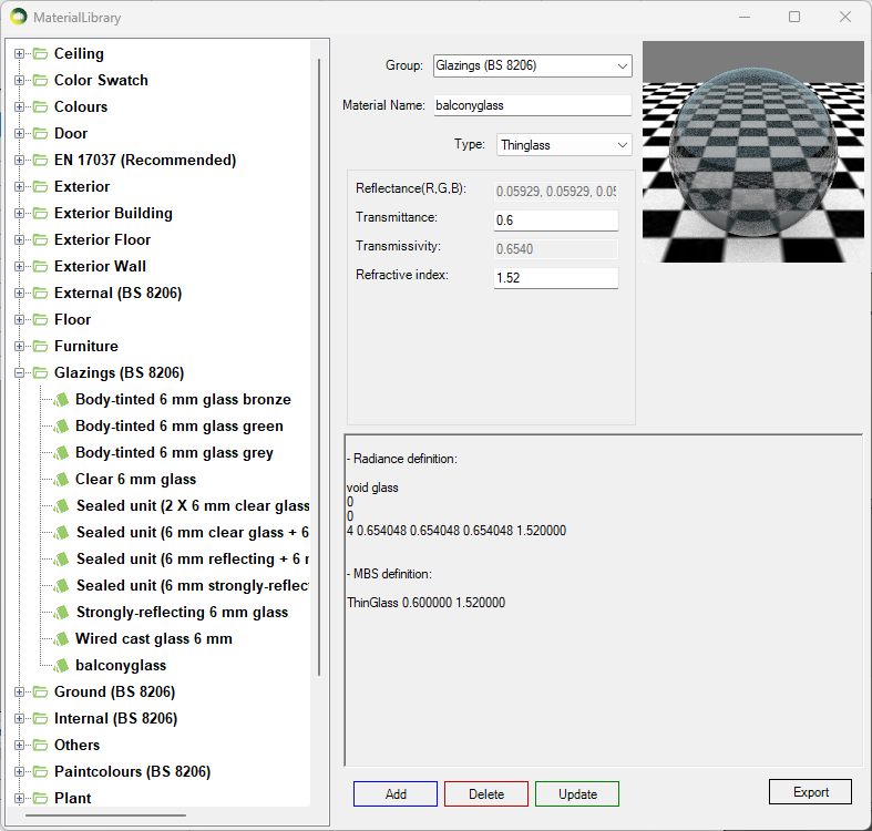
How to assign the Materials for Balconies?
- Balconies are supported for all calculations including Ray-traced based (Daylight Factor and Climate) and BRE (VSC, APSH and ADF).
- Put the balcony objects with the same transparency to a layer.
- Region or objects with single face should be used.
- Using objects with multiple faces may result in the transparency being applied multiple times.
- If the overall transparency of the balcony modelled as solid is 0.60,
- Then the ThinGlass transparency should be √0.60 i.e. 0.775
- Open Material dialogue then Press Open Library button
- Create a new ThinGlass type material
- The normal transmittance value should be in put as unit value e.g. 0.6 for 60%
- Refractive index of 1.52 is define as default.
- Press Add and Close this dialog.
- Remember to Press Apply on the Material dialogue.
- Then Assign the material to the layer with balcony objects on the Materials tab.
Refer to Updating Material For Layer topic for details.
Legend Settings
Gradient Legend
Gradient legend has five different colour options. All options except MBS and Rainbow allow the users to change the colour. The minimum and maximum values are pre-defined for all the calculation types which support legend creation. The values can be changed by the user if required. Intermediate colours are added to avoid colour contrast between values between two intervals. The breakdown of intermediate colours is as below:
- Two colour: 2 for the given colours and give value from interpolated colours field interpolated colours between them.
- Three colour: 3 for the given colours and give value from interpolated colours field is applied between first and second and second and third colour.
- Custom colour: 11 for the given colours and 10 for the mid colour between them except the last one.
- Rainbow colour: 7 for the given colours and 18 for the intermediate colours between them. (give value from interpolated colours field between each consecutive colour except the last one)
- MBS colour: 11 for the given colours and 10 for the mid colour between them except the last one.
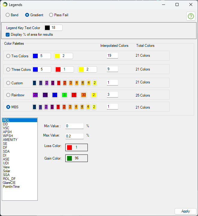
Legend interval
The interval for legend values is created by dividing the min and max values equally to the legend colours. Interval values for legend colours are calculated using the formula (Max value – Min value) / (total colours in legend – 1). The last colour is for all values greater than max therefore (total colours – 1) is used.
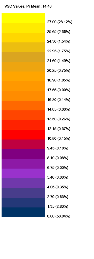
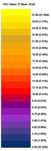
For example, The interval of values per MBS legend colour for VSC legend with min of 0 and max of 27 will be calculated as below.
(27-0) / (21-1) = 1.35
Gradient Legend is supported by the following calculations
Facade
- VSC, APSH, SE, Amenity, DF and Solar Radiation
Solids
- VSC, APSH, SE, DF
Result Images
- All room calculation types.
- ROL, DD and Amenity use these colours when Use Image Texture for Room/Amenity Results option in Application Settings is ticked.
Band Legend (Non-Gradient)
- Select the calculation type on the combo box to define a band legend values.
- Then choose a colour and enter a value. The values must be in ascending order.
- The first value will be the minimum value and last value will be maximum value for any calculation.
Band Legend is supported by the following calculations
Facade
- VSC, APSH, SE, Amenity, DF and Solar Radiation
Solids
- VSC, APSH, SE, DF
- Pass Fail legend will be used for calculation which don’t support band mode.
Result Images
- All room calculation types.
- ROL, DD and Amenity use these colours when Use Image Texture for Room/Amenity Results option in Application Settings is ticked.
Pass Fail Legend
The legend will be created with just three colours for Pass, Nearly Pass and Fail. The colours can be changed by the users. The pass values for VSC and APSH is taken from Project settings Assessment criteria section.
For Example, for VSC calculation
- if the result >= 27 (or) loss < 20 % then it passes
- if the result >= 26 (or) loss < 21 % (Tolerance = 1) the it is Nearly Passed
- otherwise it will fail.
- The legend will show Pass, Nearly Pass and Fail results.
- If the calculation is run for neighbour scheme only one legend is created.
Pass Fail Legend is supported by the following calculations only
Facade
- VSC, APSH, SE and Amenity
- Band legend will be used for DF and Solar Radiation if Pass Fail legend is set
Solids
- ROL, DD, VSC, APSH, Amenity, SE and DF
Result Images
- None
- Band legend will be used if Pass Fail legend is set
Raytracing Settings
Two Monte Carlo backward ray tracer are provided: Path tracing and Radiance software.
- Iterations N: “The error in the Monte Carlo calculation of indirect illuminance will be inversely proportional to the square root of this number:four times more samples are required to decrease the error by half.
- In Radiance option: This value corresponds to ambient divisions “–ad” parameter:
number of rays casted from the surface point to its hemisphere about the normal to estimate the radiance values. Each ray if not absorbed or terminated spawns to N more rays. - In Path tracing: Since no branching happens on each bounce this value determines the total number of indirect paths initiated from the sensor.
- In Radiance option: This value corresponds to ambient divisions “–ad” parameter:
- Indirect Bounces:
- In Radiance: This is the maximum number of diffuse bounces computed by the indirect calculation. A value of zero implies no indirect calculation.
- In path tracing: This is the minimum number of bounces. Russian Roulette probability is applied after reaching this number.
Calculation FAQs
How to name the group?
- Groups must be named precisely. EXISTING, PROPOSED and SURROUNDING
- EXISTING: For buildings/structures which are to be demolished.
- PROPOSED: For buildings/structures which are to be added.
- SURROUNDING: For buildings/structures which stay the same.
What are the steps to convert the model?
- In the Details section, select the convert checkbox next to the group in which you are interested.
- In the Conversion Options section:
- If you want to run calculations in GPU, tick on the Convert to GPU format option. It requires a compatible graphics card.
- If you want to run DF and Climate calculations in CPU, the Convert to Radiance format option must be ticked. ROL and BRE calculations on the CPU don’t require Radiance conversion.
- Tick the Use Material Table option to use a material table.
- To modify the material table, please click on Open Material button. For more details on the material settings, please refer to Material Knowledge Base.
- Click on the Convert button located at the right-bottom corner of the dialogue.
How to avoid re-converting a large surrounding every time?
- The convert option for the Surrounding group must be unticked and the Existing and Proposed group should be ticked before conversion.
- A cache file will be created on the first conversion for surrounding and any subsequent conversion will re-use that.
- If the surrounding group changes, then the cache must be cleared with the Clear Surrounding Cache button and Convert again

Can registered windows be added to any groups?
- Registered windows should be in either the Proposed or Surrounding group based on where they are.
- The same window must not be added to both the Proposed and surrounding group.
Can the conversion automatically detect interior floor, wall and ceiling surfaces?
If you tick Detect Interior Surface and Detect window Frames options, detect interior floor, wall and ceiling surfaces will be detected based on the Revit room and wall orientation and grouped together as below so materials can be applied easily.
- mbs_floors
- mbs_interiorwalls
- mbs_ceilings
- mbs_windowframe
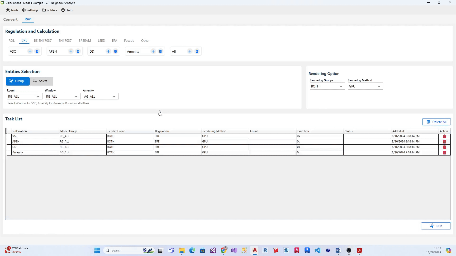
What are the steps to add calculations to the list?
- Select the relevant regulation (eg: ROL, BRE, BS EN17037). The associated calculations get displayed below each regulation.
- Set the Group on the relevant boxes.
- Click on the + icon next to the calculation name to add the individual calculation.
- Alternatively, Click on the + icon next to All to add all the calculations in the regulation.
What are the steps to add multiple groups for a calculation to the list?
- Select the relevant regulation (eg: ROL, BRE, BS EN17037). The associated calculations get displayed below each regulation.
- On Enitities Selection section, Select All option from the relevant entity (i.e. Room, Window, Amenity, Facade). Note: All option will be displayed only if there is more than one group in that particular entity type.
- After selecting the All option, click on + icon next to the desired calculation. Alternatively, you can click + icon next to All calculations if you would like to add all the groups for the calculations in the regulation to the task list.
What are the steps to modify group for calculation on the list?
- Head to the relevant task on the task list and right-click on it.
- A little popout dialogue containing the list of relevant groups for the selected calculation will appear on your screen.
- Select the required group and click on Save.
What unit is used by the software?
- Meters.
- The model will be automatically converted to meters during conversion/registration stage regardless of the unit used by Revit model.
Why are the graphical results not visible in the model?
- The room results can be shown in two different ways.
- First option is based on the Autodesk® Revit Analysis Visualization Framework.
- The second option is based on an image placed on a generic model object.
- The option can be set in Application settings Calculation tab. Second option is set by default.
- The result images created using the first option are temporary and are deleted when the model is closed. The graphical results are only visible in Shaded or Hidden line Visual Style. Load Result option can be used to recreate the result images.
- The result images created using the second option are permanent and are saved with the model. The graphical results are only visible in Realistic Visual Style. Load Result option can be used to recreate the result images.
- If the results are partially visible, check to make sure Color Fill is not blocking the results. Go to Visibility/Graphics – Rooms and Untick the Color Fill option
How is the target area calculated for room point based calculations, from the graphical result?
The target area (as in the exported report) for Daylight Distribution, Daylight Factor and Climate based calculations might not tally up exactly with the graphical results visible in the model.
This is due to the fact that the Waldram Tools software uses Autodesk® Revit Analysis Visualization Framework to represent the graphical result on surfaces while the calculations are done in MBS.
The target area for
- Daylight Factor and Climate based is simply calculated by (equally weighted) averaging the calculation points result within the room area.
- Daylight Distribution (No Sky Line) the contour is interpolated from the points result (in the same way as in Waldram Tools AutoCAD package).
How is the window frame affecting the calculations?
- It would not affect calculations, such as VSC, where the sensor is located on the outer face of the window.
- The frame if present blocks the view and daylight for all the room point based calculations such as Daylight Distribution, Daylight Factor and Climate Daylight.
- For ADF where the calculation point is behind the glazing by a small offset the frames do not take part in calculating the Sky Component (and to eventually derive the theta angle) as there is a chance that the sensor gets blocked by part of the frame. The frame factor therefore is set to 1 automatically for registered windows. And (to compensate) the glazed area is exactly calculated as the sum of all the glazing elements in the window.
What transparency value should be used for Waldram image?
- If the Waldram image based calculation (VSC, APSH, ADF) is run for Neighbour analysis, the image will combine Existing and Proposed images onto a single image.
- The transparency of the image can be set in Application Settings > Colours tab.
- Transparency :155 (or anything in middle) = Both visible
- Transparency: 0 = When overlapping, Proposed on top, Existing Hidden
- Transparency: 255 = When overlapping, Existing on top, Proposed Hidden
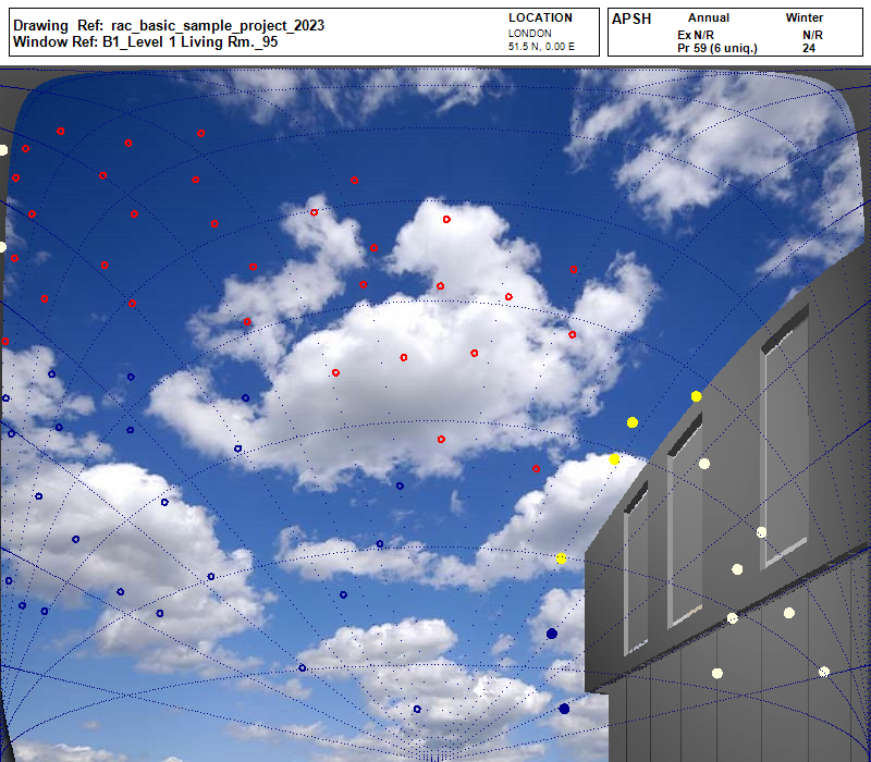
What does the colour of the dot indicate in APSH Waldram diagram?
- Dark Blue dot indicates Winter sun
- Dark Yellow dot indicates Summer sun
- light Blue dot indicates blocked Winter sun
- light yellow dot indicates blocked Summer sun
- Dot with a hole indicates that the dot is seen by more than one window in the same room.
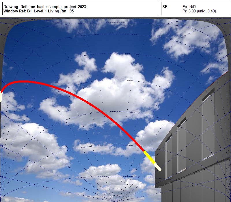
What does the colour of the dots indicate in SE Waldram diagram?
- Dark Yellow dot indicates the sun dot visible from the window.
- Light yellow dot indicates the sun dot blocked for the window.
- Red dot indicates that the dot is also seen by more than one window in the same room.
Plan View FAQs
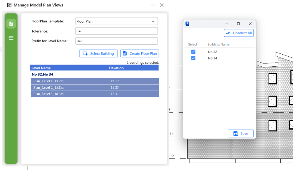
How to display results and labels in one plan view for different building elevations?
To display results and labels in a single plan view for buildings with different elevations, you need to create a custom plan view positioned at an elevation that includes the rooms in all of those buildings.
To achieve this, the software provides a tool called “Manage Model Plan Views”, which allows you to create floor plans in a structured and efficient manner within our plugin. Please follow the steps below:
- Go to Utility Tools.
- Click on Manage Model Plan Views.
- Adjust the Tolerance value in the dialog. Here, tolerance value represents the difference between the elevations of the selected buildings.
- Click on the Select Building button.
- In the building selection dialog, choose the relevant building names.
- The available plans that can be created will be displayed in the Manage Model Plan Views dialog.
- Click on the Create Floor Plan button.
How to view results in plan views?
To view the results:
- Go to Utility Tools.
- Click on Open Named Host Level Floorplan.
- A new dialog will appear, allowing you to select a Room, Window, or Amenity.
- After selecting one of these options and choosing the relevant item, the nominated plan view will open, displaying the corresponding result.
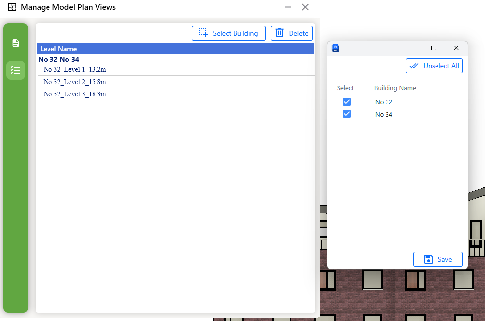
How to delete plan views?
Plan views created using Manage Model Plan Views are registered in the database. Therefore, manually deleting them from the Project Browser does not fully remove their records. To completely delete a plan view, please follow the steps below:
- Go to Utility Tools.
- Click on Manage Model Plan Views.
- In Manage Model Plan Views dialouge, click on the icon with three horizontal line (know as Manage Plan View).
- Next, Click on the Select Building button.
- In the building selection dialog, choose the relevant building names.
- Click on the Delete button.
Daylight factor
BREEAM Daylight Factor Criteria
Terms and Definitions
Average Daylight Factor
The average daylight factor is the average indoor illuminance (from daylight) on the working plane within a room,
expressed as a percentage of the simultaneous outdoor illuminance on a horizontal plane under an unobstructed CIE Standard Overcast Sky.
Point Daylight Factor
A point daylight factor is the ratio between the illuminance (from daylight) at a specific point on the working plane within a room, expressed as a percentage of the illuminance received on an outdoor unobstructed horizontal plane. The minimum point daylight factor is the lowest value of the daylight factor on the working plane at a point that is not within 0.5m of a wall.
Uniformity
The uniformity is the ratio between the minimum illuminance (from daylight) on the working plane within a room (or minimum daylight factor) and the average illuminance (from daylight) on the same working plane (or average daylight factor).
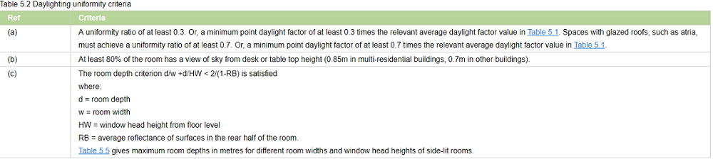
Daylight Factor Criteria
BREEAM 2018
The relevant building areas must meet
1. Minimum value of average daylight factors required
2. Daylighting uniformity criteria
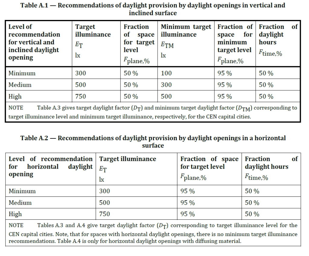
BS EN17037 Daylight Factor Criteria
Daylight Factor Criteria
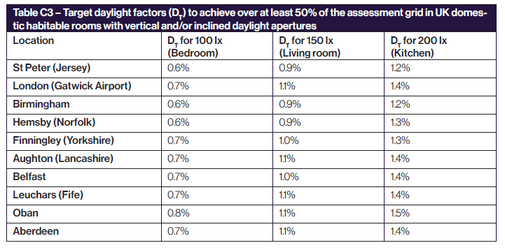
UK National Annex
The UK Annex is intended for “hard to light” dwellings.
The targets for DF is linked to the lux targets defined for BS EN17037 SDA (This can be accessed via Project Settings Climate Daylighting tab). The target DF is calculated based on the target illuminance and the median external diffuse illuminance. e.g. For London Gatwick, median illuminance is 14100. The equivalent target DF for 100 lux is (100 / 14100) % 100 % i.e. 0.7%
The target DF is to be met for 50% of the time over 50% of the space
EN17037 Daylight Factor Criteria
Daylight Factor Criteria
The targets for DF is linked to the lux targets defined for EN17037 SDA. (This can be accessed via Project Settings Climate Daylighting tab). The target DF is calculated based on the target illuminance and the median external diffuse illuminance. e.g. For London Gatwick, median illuminance is 14100. The equivalent target DF for 300 lux is (300 / 14100) % 100 % i.e. 2.1%
The target DF is to be met for 50% of the time over 50% of the space. The min target DF is to be met for 50% of the time over 95% of the space.
Setting Pass Criteria
Assessment Criteria are set per project in Project Settings dialogue > Climate Daylighting tab.
Select the regulation first and then Press the … button next to the regulation to open the Climate Criteria dialog for the regulation.
DF BS EN17037 Criteria
The criteria is set according to BS EN17037 regulation. The DF criteria are derived from the SDA criteria based on the room type and the Median diffuse horizontal illuminance for the location.
For e.g. Median diffuse horizontal illuminance for London Gatwick based on the energy plus epw file is 14100. So the equivalent DF target for Living Room will be (150/14100)*100 = 1.1
DF EN17037 Criteria
The criteria is set according to EN17037 regulation. The DF criteria are derived from the SDA criteria based on the selected space type targets and the Median diffuse horizontal illuminance for the location.
For e.g. Median diffuse horizontal illuminance for London Gatwick based on the energy plus epw file is 14100. So the equivalent DF target for 300 Lux will be (300/14100)*100 = 2.1
BREEAM DF Criteria
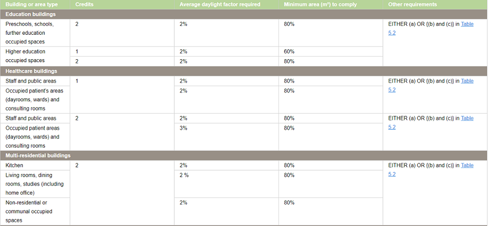
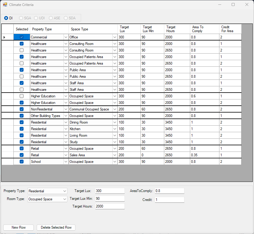
All the entries on BREEAM Regulations Table 5.1 are predefined based on the BREEAM New Construction 2018 and loaded as default in Criteria table dialogue.
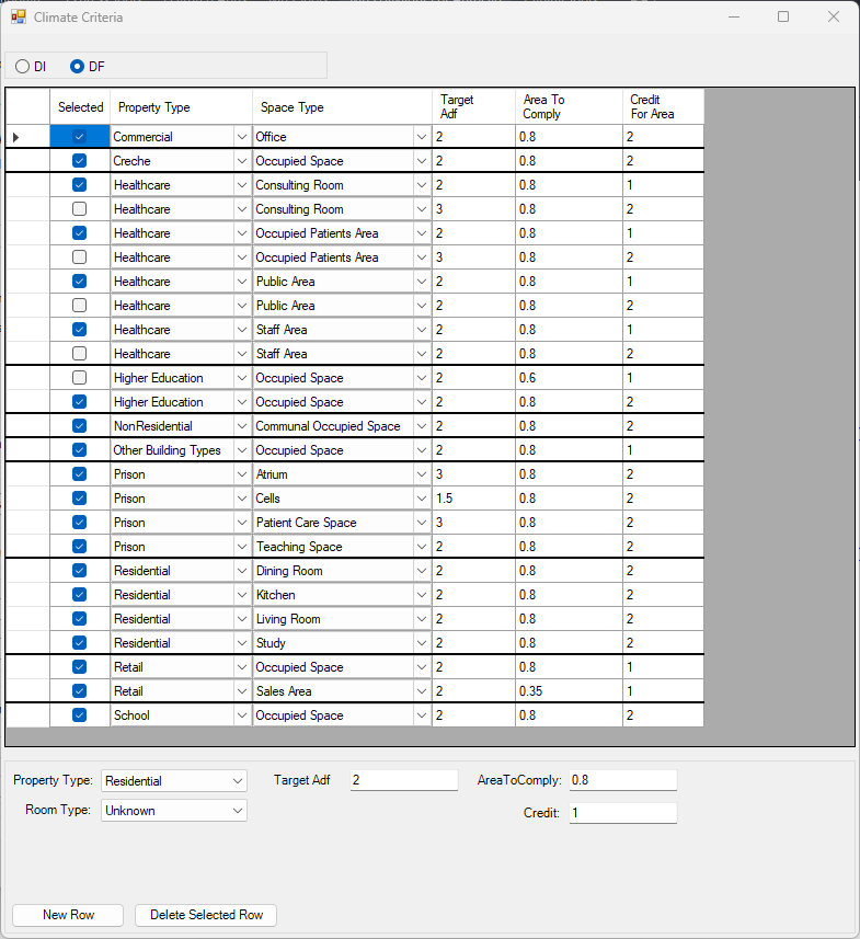
Each property and room type pair in BREEAM Regulations Table 5.1 is translated into one or two rows(based on number of credits, target lux, occupied hours) in the dialogue.
If a property, room type pair has different credits or target DF, one row is added for each credit in the table dialog.
For example, Higher education occupied space can achieve 1 credit with 60% area with 2% and 2 credits with 80% area with 2%
Two records are added to the table with the corresponding values for credit value and target DF.
The first entry for higher credit is selected for calculation.
– To Delete an existing criterion select the row on the table and press the Delete Selected Row button.

To Add new criterion fill in the text boxes with corresponding criterion and press the New Row button. Note that the AreaToComply column takes value between 0 – 1.
– To Update an existing criterion simply change the values on the table.
The Selected column displays the criteria that are set for calculation. The DF calculation uses the
registered property and space type of a room to query its assessment criteria from the above table. If more than one records exists for this property and room type, the Selected is returned from the table. If no records exists the default “Other Building Types” and Occupied Space criterion is used.
Notes for All DF Criteria
Note 1: The output report displays criteria that has been set prior to running the calculation.
In other words the selected criteria record is saved against the room on calculation time and same criteria is queried at report time.
Note 2: Changing the Selected criteria, changes to Target DF, Target DF Min requires re-running the calculation.
“Area To Comply” and “Credit For Area To Comply” does not require rerun.
Steps to run Daylight Factor Calculation
- Put the objects in the model in specific layers. e.g. walls in “wall” layer, any external obstructions in “external” layer and so on.
- The registered windows will automatically get Glass material based on their properties set during the registration time.
However the registered windows must be added to relevant group before conversion.
For more details on how to setup the model for running Daylight Factor, utility commands that automate the process and questions on Window Glazing Transmittance,
please refer to the topic How to prepare a model for Assigning the Materials? in Materials knowledge base section. - Open the Material dialog and assign a material for each layer. Material Library has a predefined list of most of the common materials. Yet you can define your own or customize them.
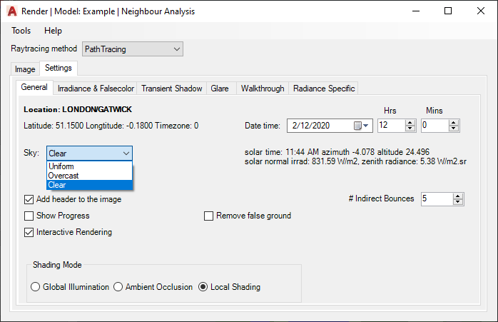
For more details on how the material dialogue works please refer to the About Material Dialog topic in Materials knowledge base section. - Set the Ray tracing Method and its options on Application Settings > Calculation tab > Ray Tracing section.
- The Sky distribution used for Daylight Factor is CIE Overcast Sky. However this can be changed to Uniform Sky on Project Settings dialogue > Calculation tab for experimental purpose.
- Tick Convert to Radiance format or Convert to GPU format before Converting the model.
- Set climate regulation to BREEAM, BS EN17037 or EN17037
- Finally run the calculation using the CPU or GPU rendering method
Climate Based Calculations
BS EN17037 Illuminance (SDA) Criteria
Illuminance Criteria
UK National Annex
The UK Annex is intended for “hard to light” dwellings.
The illuminance targets for BS EN17037 SDA can be accessed via Project Settings Climate Daylighting tab.
The target Lux is to be met for 50% of the time over 50% of the space.
Notes (Also Applies to EN17037 Criteria too)
- Daylight Hours: The hours of daylight are determined by rank-ordering (i.e. from highest to lowest) the 8760 values for diffuse horizontal illuminance and then extracting the first (i.e. the highest) 4380 hourly values. Note that the retained (i.e. highest) 4380 values may include some zero values, or that the discarded 4380 values may include some non-zero values.
This is to be expected given the nature of illuminance data in climate files and does not affect the outcome. - The relevant area of the space plane covers the entire space, and is located 0.85m above the floor.
- A perimeter area is excluded from the area of the space, because locally, illuminances are not relevant to the assessment of daylight provision, since the illuminances can be excessively high (near windows) or excessively low, next to opaque walls. A perimeter area is the area located next to the walls of the space, and should be excluded in daylight calculations.
EN17037 Illuminance (SDA) Criteria
Illuminance Criteria
The illuminance targets for BS EN17037 SDA can be accessed via Project Settings Climate Daylighting tab.
For spaces with daylight openings in vertical and inclined surface, The target Lux is to be met for 50% of the time over 50% of the space. The min target Lux is to be met for 50% of the time over 95% of the space.
For spaces with daylight openings in horizontal surface, The target Lux is to be met for 50% of the time over 95% of the space. There is no minimum target lux.
BREEAM Illuminance (DI) Criteria
Terms and Definitions
Average daylight Illuminance
Daylight illuminance for all points in the space for a specific hour (e.g. 1st Jan 8 AM) is averaged. If this average is over the target lux (e.g. 300 lux) value, the hour will count towards the achieved hour for the target lux.
Minimum Daylight Illuminance
The lowest point daylight illuminance in the space at a specific hour e.g. 1st Jan 8 AM) on the working plane within a room. The minimum point daylight factor is the lowest value of the daylight factor on the working plane at a point that is not within 0.5m of a wall. If this lowest lux value is over the target lux min value (e.g. 90 lux), the hour will count towards the achieved hour for the target lux min.
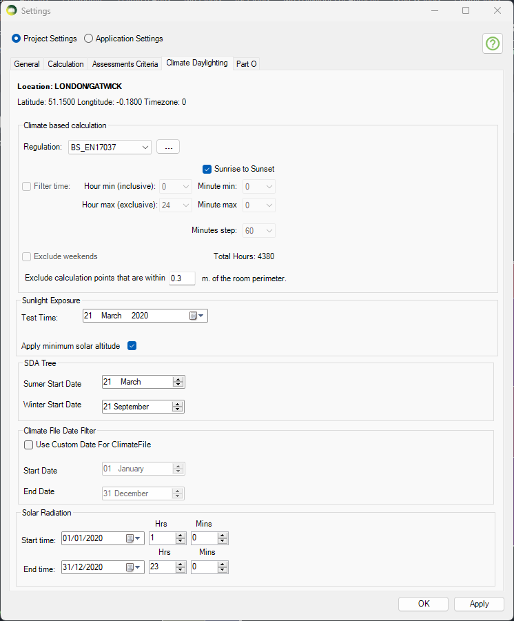
Setting Weather Location and Hours
Setting up Weather data and Location
Select location for climate based calculation on Project Settings dialogue > General tab > Location section. All weather data files must be in epw format and located in below folder:
Autocad: %appdata%/MBS Software/DaylightForAutocad/Climate Files
Revit: %appdata%/MBS Software/DaylightForRevit/Climate Files
For new locations, the .epw file (IWEC format) can be downloaded from the energy plus website.
- Select the region then the country then the location and then select epw to download the file.
- Once downloaded copy the .epw file to the above appdata folder which can be opened by clicking the Folder icon next to the climate file location combo box.
This setting is project specific and needs to be set per job.
Setting up Climate Hours
- Before running the calculation, the regulation and annual daylight hours options have to be set through Project Settings > Climate Daylighting tab.
- The test has to be run separately for each regulation. Results are saved per regulation and thus once they are calculated, corresponding reports could be outputted without a re-run.
- The recommended daylight hours for BREEAM, BS EN17037and EN17037 is Sunrise to Sunset.
- For BS EN17037 and EN17037, 50% of the hours with the highest illuminance (4380 hours) is used instead of all the hours between sunrise and sunset.
- The filter hour is inclusive for the start hour and exclusive for the end hour.
For example, if the occupancy starts at 9 AM and finishes at 5PM, the filter hour should be set to 9 to 17 (8 Hour Occupancy)
Setting Pass Criteria
Assessment Criteria are set per project in Project Settings dialogue > Climate Daylighting tab.
Select the regulation first and then Press the … button next to the regulation to open the Climate Criteria dialog for the regulation.
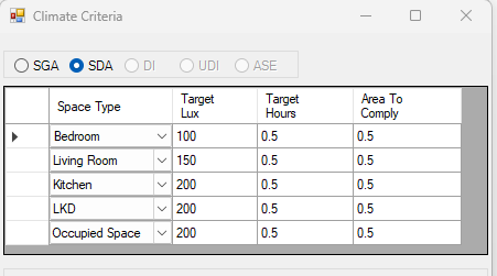
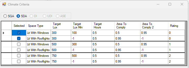
SDA BS EN17037 Criteria
The criteria is set according to BS EN17037 regulation. The criteria are set based on the space type.
SDA EN17037 Criteria
The criteria is set according to EN17037 Regulation. The criteria are fixed and grouped by their rating. The Selected criterion is queried and used for calculation.
BREEAM DI Criteria
All the entries on BREEAM Regulations Table 5.3 are predefined based on the BREEAM New Construction 2018 and loaded as default in Criteria table dialogue.
Each property and room type pair in BREEAM Regulations Table 5.3 is translated into one or two rows(based on number of credits, target lux, occupied hours) in the dialogue.
If a property, room type pair has different credits, target lux or occupied hours one row is added for each credit in the table dialogue.
As an example, below Staff room type in Healthcare property has two entries for 1 Credit and 2 Credit with different occupied hours.
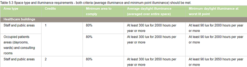
Two records are added to the table with the corresponding values for credit value, target lux and occupied hours.
The first entry for credit 1 is selected for calculation.
– To Delete an existing criterion select the row on the table and press the Delete Selected Row button.

To Add new criterion fill in the text boxes with corresponding criterion and press the New Row button. Note that the AreaToComply column takes value between 0 – 1.
– To Update an existing criterion simply change the values on the table.
The Selected column displays the criteria that are set for calculation. The DI calculation uses the
registered property and space type of a room to query its assessment criteria from the above table. If more than
one records exists for this property and room type, the Selected is returned from the table. If no records exists
the default “Other Building Types” criterion is used.
Notes for All Climate Criteria
Note 1: The output report displays criteria that has been set prior to running the calculation.
In other words the selected criteria record is saved against the room on calculation time and same criteria is queried at report time.
Note 2: Changing the Selected criteria, changes to Target Lux, Target Lux Min, Target Hours requires re-running the calculation.
“Area To Comply” and “Credit For Area To Comply” does not require rerun.
Steps to run Climate-Based Calculation
- Put the objects in the model in specific layers. e.g. walls in “wall” layer, any external obstructions in “external” layer and so on.
- The registered windows will automatically get Glass material based on their properties set during the registration time.
However the registered windows must be added to relevant group before conversion.
For more details on how to setup the model for running Daylight Factor, utility commands that automate the process and questions on Window Glazing Transmittance,
please refer to How to Setup a model for Assigning the Material? topic in Materials knowledge base section. - Open the Material dialogue and assign a material for each layer. Material Library has a predefined list of most of the common materials. Yet you can define your own or customize them. For more details on how the material dialogue works please refer to About Material Dialog topic in Materials knowledge base section.
- Set the Ray tracing Method and its options on Settings > Ray tracing method
- Tick Convert to Radiance format or Convert to GPU format before Converting the model.
- Set climate regulation to BREEAM, BS EN17037 or EN17037 or LEED or EFA
- Select SDA or DI calculation
- Finally run the calculation using the CPU or GPU rendering method
BREEAM DI Results
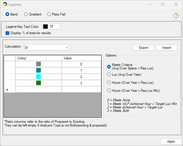
The DI results can be presented visually in 4 different ways.
- As shown in the image, the Meets criteria option will show a single colour image for the room based on whether Achieved hour > Target Lux and/or Worst lit point achieved hour > Target Lux Min are met or not.
- Please note that the rest of the three options are alternative presentation of the result and do not show the achieved hour for target lux and target lux min as averaged over the space
- The Lux (Avg Over Year) option can be used to show the average lux achieved by each point in the room over the year.
- Hours (Over Year > Req Lux) option can be used to show the number of hours when each point in the room achieve the req lux.
- Hours (Over Year > Req Lux Min) option can be used to show the number of hours when each point in the room achieve the req lux min.
The DI Excel result contains the results for the main criteria as well as some alternative results.
As shown in the DI criteria results image,
- The Req Lux Achieved Hours column shows the total number of hours when lux value averaged over the space is at least 300 Lux.
- The WLP Achieved Hours column shows the total number of hours when the worst lit point lux value (except foe the points within 0.5m of the wall) is at least 90 Lux.
- The Meets Criteria column shows Yes, If both Req Lux Achieved Hours and WLP Achieved Hours are more than the 2000 hours (Req hour per year).
The Alternative result columns are to the right of the Meets criteria column and are added to give alternative results for each points over the year.
- The Avg Annual Lux column shows the average lux value based on the average lux achieved by all the points in the room. Each points average lux value can be shown by using the Lux (Over the year) option in Legend settings.
- The % of Area Meeting Req Lux column shows the percent of the points which have an average of at least 300 Lux.
- The Avg Annual Achieved Hours column shows the average achieved hours value based on the achieved hours with at least 300 lux achieved by all the points in the room. Each points achieved hours with at least 300 lux can be shown by using the Hours (Over Year > Req Lux) option in Legend settings.
- The % of Area Meeting Req Hours column shows the percent of the points which achieve 2000 hours with at least 300 Lux.
- The Avg Annual WLP Achieved Hours column shows the average achieved hours value based on the achieved hours with at least 90 lux achieved by all points in the room. Each points achieved hours with at least 90 lux can be shown by using the Hours (Over Year > Req Lux Min) option in Legend settings.
- The % of Area Meeting Req Hours (WLP) column shows the percent of the points which achieve 2000 hours with at least 90 Lux.
BREEAM Calculations
SDA Calculation With Trees
In order to include Trees in the SDA annual calculation, the new Annualtree material should be used. It combines the existing TransTree material to specify Summer and Winter materials for trees. The dates for Summer and Winter trees is specified in Project Settings > Climate Daylighting. This is a special material for SDA calculation and should not be used with any other calculations.
e.g. if the Annualtree material is used with Summer Start Date 21 March and Winter Start Date 21 September then the SDA calculation is run once for the Summer date e.g. 21 March to 20 September using the Summer tree material and once for the Winter date e.g. 21 September to 20 March using the Winter tree material. The results are then combined to give an overall annual result.
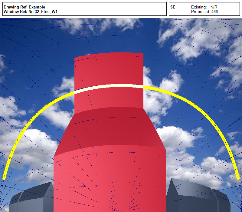
Sunlight Exposure
Minimum recommendation
This is to be checked in the reference point at the centre of the window width and at the
inner surface of the aperture (façade and/or roof). For multiple apertures in different façades it is possible to cumulate the time of sunlight availability if not occurring at the same time. The reference point is minimum 1.2 m above the floor and 0.3 m above the window sill (whichever is higher).
NOTE 1 To allow flexibility for rooms orientation the angle of window normal αwn,s = 120° measured from South and the minimum sun height γs,min are applied. Solar altitudes below those stated in Table D.1 (BS EN17037 guide) are neglected in the evaluation.
Minimum recommendation for exposure to sunlight
The minimum recommendation is that the room should receive possible sunlight for a duration higher than 1.5 hours (supposed to be cloudless) on March 21.
Table A.5 proposes three levels for exposure to sunlight.
| Recommendation | Sunlight Exposure (Hours) |
| Minimum Exposure | >= 1.5 |
| Medium Exposure | >= 3.0 |
| High Exposure | > 4.0 |
Table A.5
Run calculation
The test date can be changed on Project Settings > Climate Daylighting tab.
The default date is set for March 21.
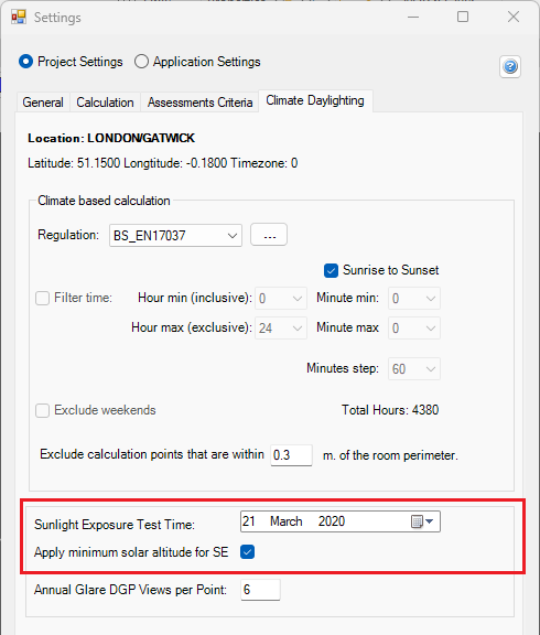
Open Run dialogue and select Sunlight Exposure to run the calculation.
Glare Analysis
Annual Potential Glare
Specular material that reflects Sun beam directed towards the view point is detected
as glare source and is marked in colour banding on the image.
Steps to create the Annual Potential Glare image and report
1. Set the location in Project Settings > General tab by selecting the weather file.
2. Assign specular material (ThinGlass, Mirror, Metal and Plastic) in Material dialogue to all surfaces that are considered to be potential for reflecting glare. All registered windows are
automatically applied ThinGlass material and no material definition is needed in the material dialog.
3. Open the Render dialogue. Select the view point and direction either by entering the
coordinates or picking them from the model by pressing the button next to the input boxes.
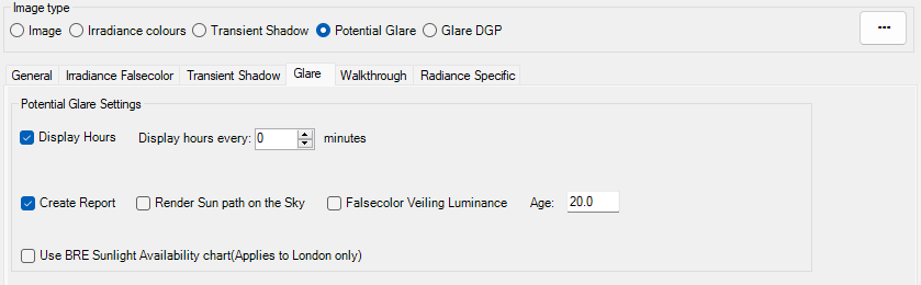
4. Select Potential Glare option
5. Change Camera type to Fisheye and set the view angle accordingly.
The view angle for fisheye is between 0 to 180.
6. Optionally change the driver’s age. Default age is set to 65 to give the worst case result.
7. Display Hours option can be ticked to show the time on the image. If the Display hour every is set to Zero, then only the hour texts are shown e.g. 08:00 or 09:00.
If the Display hour every set to non zero value e.g. 15, then the hour and minute for the interval will be shown e.g. 08:15 or 08:30. This option can cause the image creation to take longer for smaller minute intervals.
8. Tick “Create Report” option to generate csv report for the rendered image.
The report contains information for every pixel that has glare occurrence.
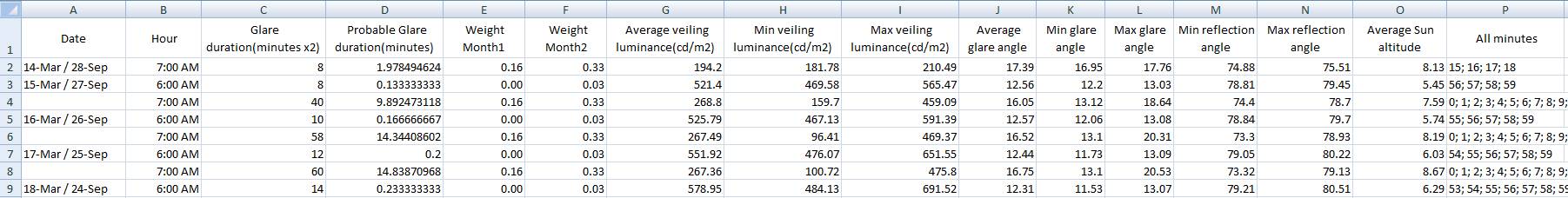
This includes date and time, glare intensity in cd/m2, distance from the glare, field of view angle of the glare.
The report and images are saved in the [Model_Name]_Waldram/Images/GlareTest folder.
9. Start the Subpixel sample with at least 50 and Increase it by 25 to render a sharp image. The noise in the image is inversely proportional to the square root of this number. The image on the right is rendered with 50 subpixel samples and is little bit blurry so it should be rendered with higher subpixel samples.
10. Press Render button.
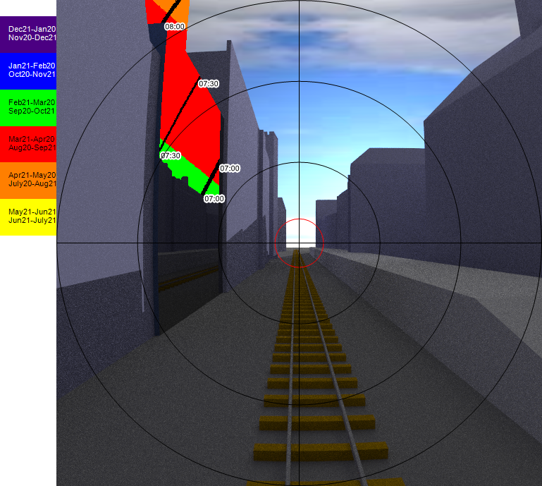
Understanding the image output
- Circles
- The circles in the image represent 10 degree steps except the first and sometimes the last step.
- The image on the right side is created using a view angle of 60 degrees. The inner most red circle is a special one added to represent the 3 degrees of view angle (6 degree in total which is affected the most). The next three lines are for 10, 20 and 30 on each side and thus totalling the 60.
- If the view angle is not a multiple of 20, then the last one will be the half of the view angle. e.g. if the view angle of 70 is used, then the circle lines will be for 3, 10, 20, 30 and 35.
- Colours
- The colours in the glazed surfaces represent the colours for the month when the potential glare occurs.
- A legend with the month name and the colours can be added to the rendered image by going to Render dialogue options > General tab and ticking Add header to the image option.
Glare DGP
For the assessment of daylight glare EN17037 please refer to the annual potential glare.
This is a point-in-time calculation. Radiance evalglare program is used to calculate DGP value.
According to En17037 glare is defined as:
“Condition of vision in which there is discomfort or a reduction in the ability to see details
or objects caused by an unsuitbale distribution or range of illuminance, or by extreme
contrasts.“
DGP is defined as:
“the probability that a person is disturbed instead of the glare magnitude as a glare
measure. This new probability function is called daylight glare probability, DGP“.
It is an approach to consider both illuminance at eye level and individual glare sources of high luminance to estimate the fraction of dissatisfied persons.
According to En17037:
“DGP can be applied to any daylight oriented indoor space which is mainly side-lit and where the expected tasks are comparable to office tasks.“
| Criterion | Daylight Glare Probability(DGP) |
| Glare is mostly not-perceived | DGP <= 0.35 |
| Glare is perceived but mostly not disturbing | 0.35 < DGP <= 0.40 |
| Glare is perceived and often disturbing | 0.4 < DGP <= 0.45 |
| Glare is perceived and mostly intolerable | DGP >= 0.45 |
Steps to render an image for DGP calculation
- Set the climate file location Project Settings > General tab
- Set the Raytracing method to Radiance in Application Settings > Ray tracing tab
- Set the Sky to clear CIE sky type Settings > Ray tracing tab.
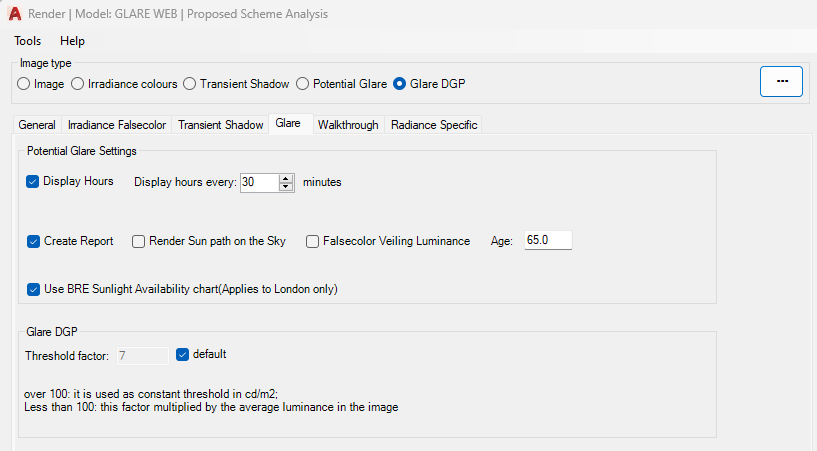
Note: changes to sky type requires model re-conversion for Radiance option. - As this is a point-in-time calculation, location, date and time have to be set in advance via Render dialog Options > General tab (Click on the … button on the render dialog to open the options).
- The default Glare DGP threshold is 7 and it can be changed in Render dialog options > Glare tab.
-
Based on the provided threshold either of the two methods are used for detection of glare sources:
-
Method A: Calculate the average luminance of the entire picture and count every section as a glare source that is x-times higher than the average luminance. For this method try values less than 100: this factor multiplied by the average luminance in the entire picture will be used as threshold for detecting glare sources.
-
Method B. Take a fixed value and count every section as a glare source that is higher than the fixed value. For this method try values over 100: the value is used as
-
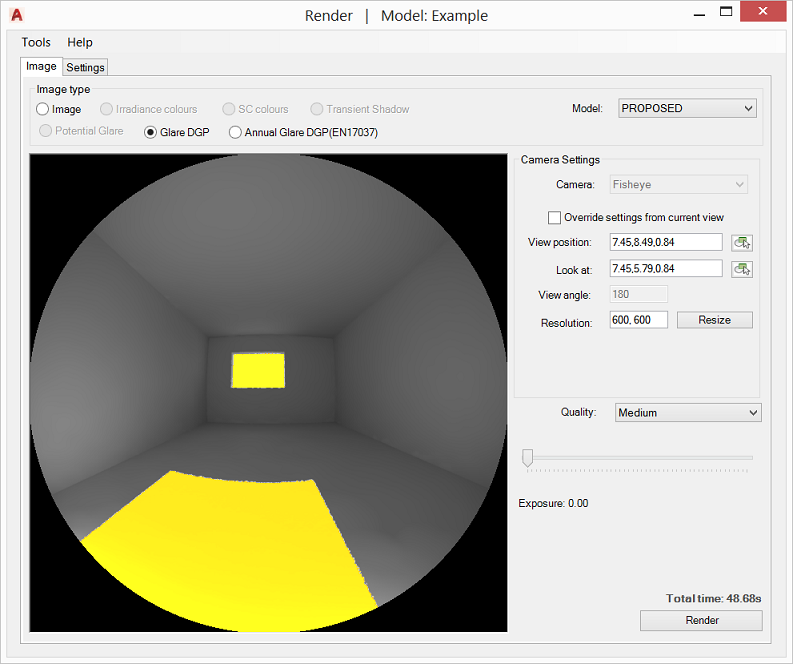
- Select a view point either by providing the coordinates on the input box or picking a point within the room (working plane).
- The camera type automatically is set to Fisheye. Set the field of view angle as required.
- Set the desired image quality and press Render. The yellow areas on the image displays the glare sources.
-
DGP value along with other glare metrics are calculated and saved in a text file in the [Model_Name]_Waldram/Images/GlareTest folder.
EN17037:
Testing position should be either a current used position of a person(workplace or often used position) or a position, which might be used and which might have a glare problem.
Such positions are usually close to the facade and/or facing facade orientations.
The viewing direction of the measurement devices should face towards the facade parallel to the floor and towards the azimuth direction of the sun. The height of the view point should be in 1.2m height.
Rendering
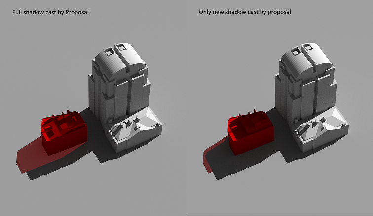
Transient Shadow Analysis
Objects in Proposed and Existing group would cast shadows same colour as their material colour. Transient Shadow Test image can be rendered using CPU or the GPU.
- Open the Application Settings > Calculation tab and choose the desired Rendering method. (GPU render require a compatible NVIDIA graphics card)
- Specify location by selecting the corresponding climate file location in Project Settings > General tab
- Open the Render dialog options > Transient Shadow tab and set the required test start and end time.
- Set the required interval (in minutes).
- The individual equinox dates can be easily set by selecting the desired date from the combo box.
- The Run All Dates option can be ticked to run for three dates 21 March, 21 June and 21 December in one Render. The times are in GMT.
- In Image tab select Shadow Test and pick the model group from the box.
- Set Camera mode to Perspective.
- Camera position and look At can be set in two ways: A. Either tick the “Override settings from current view” to setup the camera to the current view or a predefined camera. This option works better in AutoCAD Perspective mode. B. Press the View Position box button to select the position from the model. Repeat the process for Look At.
- Horizontal field of view is set via View Angle box. The effect is similar to zoom in or out.
- The image box can be resized manually through resizing the dialogue or by setting the desired resolution in Resolution box and pressing the resize button.
The resolution can also be manually be set to a value bigger than the display screen. - Set pixel samples number and press Render. The noise is inversely proportional to square root of this number: four times more samples are required to decrease the error by half.
- The shadow images are saved in the [Model_Name]_Waldram/Images/ShadowTest folder. Image file name will include the day, month and the time. No image is created for the times where the sun is not present e.g. after the sunset.
A background texture image can be set by inserting a Raster image into the model. Make sure the image belongs to either of the analysis groups.
Tick the New Shadow Only option to exclude part of the coloured shadow that already is rendered under the existing scenario.
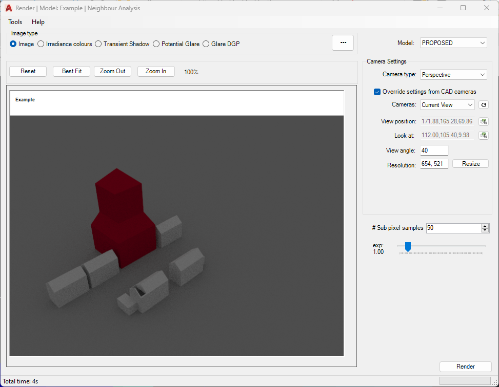
Normal Image
- Open the Render dialogue
- Specify location by selecting the corresponding climate file in Project Settings > General tab.
- Pick Radiance or PathTracing from the Render dialog options > General tab > Raytracing Method combo box.
- Also Set sky type, date and time on the same tab.
-
Select Existing or Proposed model from the Model box.
-
Camera position and look At can be set in two ways: A. Either tick the Override settings from current view to setup the camera to AutoCAD current view. This option works better in AutoCAD Perspective mode. B. Or press the View Position box button to select the position from the model. Repeat the process for Look At.
-
Horizontal field of view is set via View Angle box. The effect is similar to zoom in or out
- The image box can be resized manually through resizing the dialogue or by setting the desired resolution in Resolution box and pressing the resize button. The resolution can also be manually be set to a value bigger than the display screen.
- Set pixel samples number and press Render. The noise is inversely proportional to square root of this number: four times more samples are required to decrease the error by half.
Optional Settings under the Options > General tab:
- Picture box image can display the progress by ticking the “Show Progress” option.
- Tick Interactive rendering to pan / orbit the rendered image within the picture box. Hold left mouse button down to pan the image. Hold right mouse button down to rotate the image.
Shading Modes
There are three Shading mode supported in Path tracing mode:
- Global Illumination which produces unbiased path-traced simulation of light paths. This is the default mode.
- Ambient Occlusion option accounts only for the visiblity term. A cosine-weighted visibility factor calculated for the hemisphere of a surface point. An example is demonstrated here.
- Local Shading mode quicken the rendering but removing diffuse inter-reflection from calculation. Phong-shading model is used to render materials with pre-defined three directional lights.
Irradiance and Sky Component image
The process is same as described for rendering normal images. The maximum range of legend colours is set in Render dialog Options > Irradiance and Falsecolor tab.
The minimum is always set to zero. The maximum value can be set and is interpreted as follow:
- Values between 0 to 100 is used as Daylight Factor or Sky Component ratio.
- Values above 100 are taken as absolute lux value.
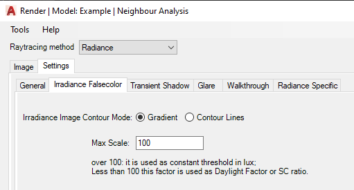
If Radiance is selected as the rendering method, two false color image modes are provided:
– Gradient option produces smooth interpolation between values on the image.
– If contour lines are desired rather than just false color image, the Contour Lines option can be used. These lines are placed over the normal Radiance picture rather than falsecolor image.
– Contour Bands produces contour bands instead of lines, where the thickness of the bands is related to the rate of change in the image.
Note:
Radiance falsecolor image uses pre-defined Radiance pm3d colour palette with 8 colours.
The image on the side shows daylight factor gradient image with corresponding values set in legend, for an indoor scene.
An hdr file format is saved along the png format, loaded through Tools > Load hdr image, which can be used to display the image with different legend colours without re-rendering the image.
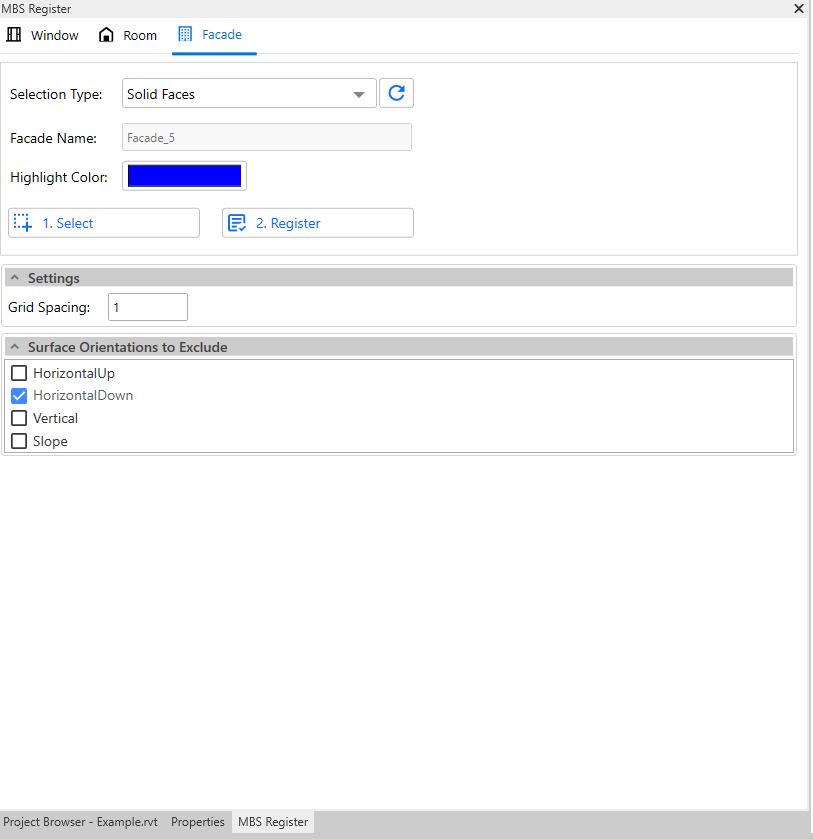
Façade Analysis
Registration Steps
- Open the Register Dialogue by clicking
 icon from menu bar.
 - Go to Facade Tab
- Enter the Grid Spacing and select the Highlight Colour (Selected
objects are highlighted using this colour) as per your requirement. - Type name for facade in the Facade Name field. Alternatively, you can enable the auto name option from settings which will add the facade name automatically.
- Auto Naming option can be enabled/disabled from Register section in Application Settings. Similary, you can also set your own custom prefix to be used for facade name.
- Facade mapping can be done for
- Solid faces
- Select the objects.
- Select button can be used multiple times to add objects in different parts of the model. Text message next to select and register bottom shows the total objects which are selected which should also be highlighted using the Highlight Facade colour. Button next to text messsage can be used to clear selected facade before registration.
- Click on Register.
- It is also possible to create a group with objects supported for Facade registration (group name must start with FG_ ). The group then appears in the Selection Type list.
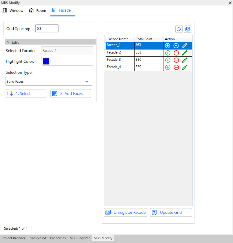
Modify Steps
- Open the Modify Dialogue by clicking
 icon from menu bar .
 - Go to Facade Tab.
From modify dialog, you can add / remove faces, rename facade, update grid spacing and unregister the selected facades.
Note: If the recently registered facade is not shown in the table, click on the Reload button above the table, which will repopulate the table.
Add Face
- Click on the + icon in the table. This will show a new section called edit below the Grid Spacing section.
- Choose the type of object you want to select from the model in the Selection Type option.
- Click 1. Select.
- Select the relevant face you want to add. After selection, the selected count gets displayed as a text message below the buttons.
- Next, click on 2. Add Faces. This will append the selected faces with existing faces.
Remove Face
- Click on the – icon in the table. This will show a new section called edit below the Grid Spacing section.
- Choose the type of object you want to select from the model in the Selection Type option.
- Click 1. Select.
- Select the relevant face you want to remove. After selection, the selected count gets displayed as a text message below the buttons.
- Next, click on 2. Remove Faces. This will detach the selected faces from the facade.
Rename Facade
- Click on icon. This will show a new section called Rename.
- Enter the desired name you want to give for the selected facade in Facade Name field.
- Click on Rename button. This will update the name of selected facade in table.
Upgrade Grid Spacing
- Select the Facades from the table. (You can select multiple facades at once.)
- Enter the desired Grid Spacing in the Grid Spacing field.
- Click the Update Grid button. The Total Point column gets updated once the grid point update is complete.
Unregister Facade
- Select facades in the the table. (You can select multiple facades at once.)
- Click on Unregister Facade button.
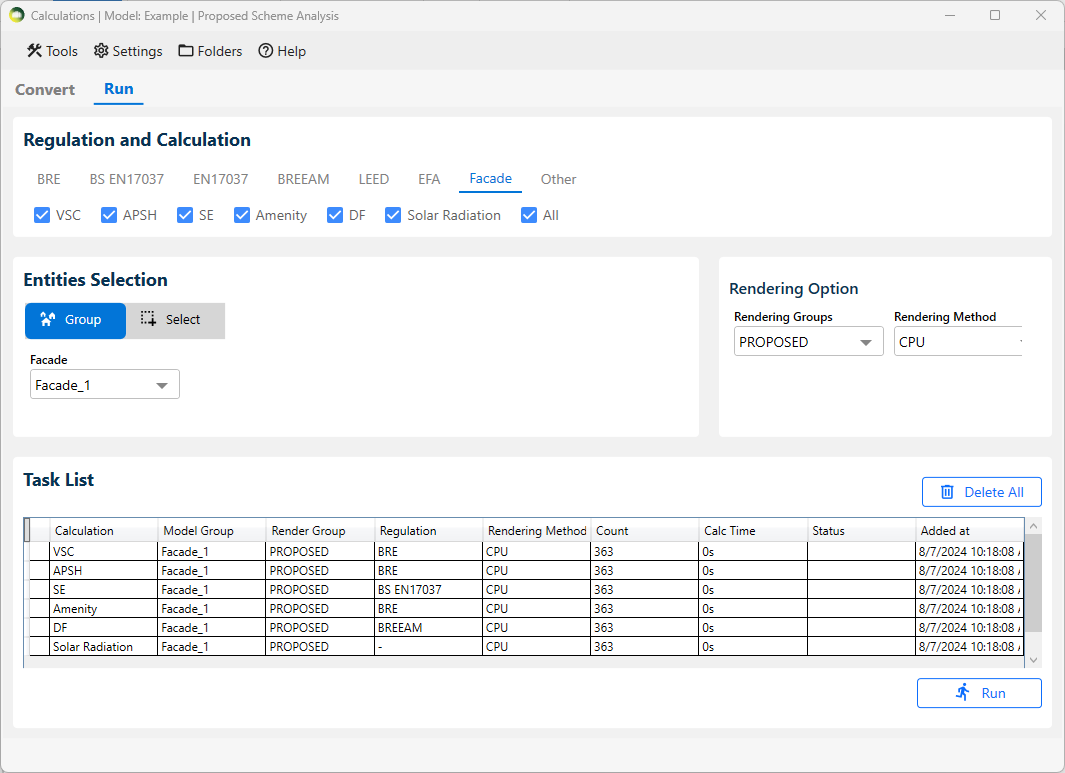
Calculation Steps
- Open the Calculation dialogue and convert the model groups by clicking the Convert button at the bottom right in the Convert tab.
- Go to the Run tab.
- Under the Regulation and Calculation section, click on the Facade Tab. All the supported calculations for Facades are listed under this tab.
- Select the calculation type by clicking on the tick box and change the Facade Name from the dropdown box displayed in the Entities Selection section if required.
- All option from the Facade dropdown can be used to add all the registered facades in one go for selected calculation.
- Before running, make sure the settings are right.
- Open Legends dialogue, you can select either Gradient or Bands.
- To get results on legend select “Display % of area for results” option. See Legend Settings Section for more details.
- After changing the Settings, click on OK.
- Open Application Settings > Calculations tab, enter Sky sub division angle for VSC calculation (5 degree is suggested).
- Click the Run button at the bottom right in the calculations dialogue to run the calculation.
Result Steps
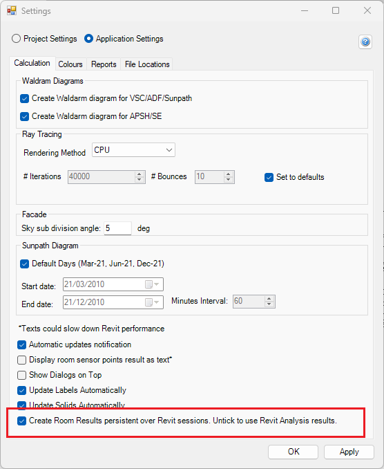
- The facade results can be displayed as Revit Analysis Result or as image on a solid face.
- The option is Application Settings > Calculation tab (Create Room/Facade Results persistent over Revit sessions. Untick to use Revit Analysis Result)
- Each calculation has its own layer (ex: FACADE_1_VSC_PROPOSED_FACADE).
- If you select “both” groups you also get the loss (ratio of proposed and existing) in its own layer (ex: FACADE_1_VSC_LOSS_FACADE).
- Use Realistic visual style as facade result colors are not visible in Wireframe view.
- The facade legend can be found in [Model_Name]_Waldram\images\FacadeLegend folder. The image on the right is created for VSC Proposed using a Gradient mode.
- CSV report are automatically created in [Model_Name]_Waldram\Reports folder.
Clear Facade Result
- Open Calculation dialogue.
- Click on Tools in menu bar.
- Click on Clear results > Facade Results.
How can I get the facade results back when I reopen the model?
- This is only necessary if Revit Analysis Result is used
- The facade results are stored as Analysis results in Revit and are not saved after the Revit session closes.
- They can be recreated by reloading the results.
Load Facade Result
- Open Calculation dialogue.
- Click on Tools in menu bar.
- Click on Load results
- Browse for the Facade result (.out file)
- Press Load
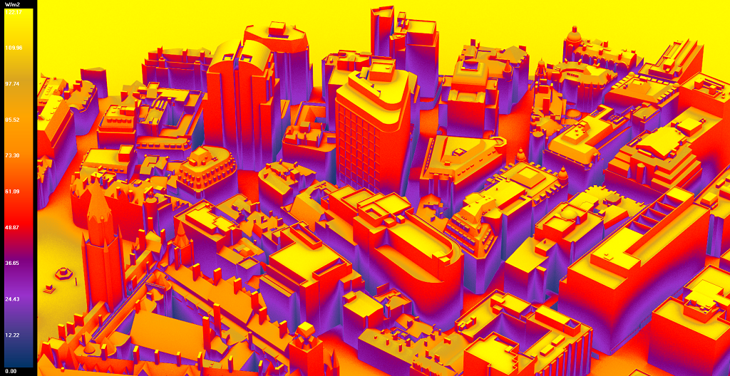
Solar Radiation
Solar Radiation
Solar Radiation can be run as a Facade calculation, the model must be converted to Radiance and thus requires Radiance to be installed on the computer.
The test date can be changed on Project Settings > Climate Daylighting tab. The default date is set for 01 Jan to 31 Dec
- This is a an annual cumulative Solar radiation calculation.
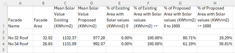
- The final output is given in KWh/m2
- The calculation is based on the epw climate file.
- The calculation includes direct contribution from the sun on cloudy condition (as per the climate file) and also includes the contribution from the atmosphere.
- A legend image and CSV report are created during the calculation.
- The CSV report includes values for all the ranges that are defined in the Legends settings. The default is set to 0 to 1000 Kwh/m2
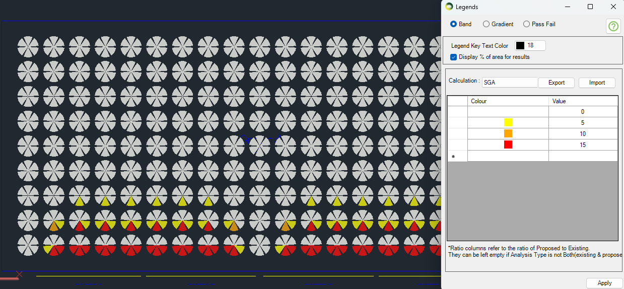
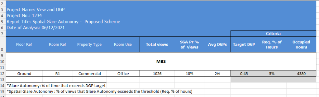
Spatial Glare Autonomy
Spatial Glare Autonomy (SGA)
- This is an annual DGP calculation (Daylight Glare Probability).
- DGP is calculated against a threshold of 0.45. This can be changed in Project Settings > Climate Daylighting > EN17037 Criteria.
- Each grid point in the room will have multiple view points (6 by default). This can be changed in Project Settings . Climate Daylighting > Annual DGP views per point.
- The visual result as shown in the image shows the % of time each view point exceeds the threshold of 0.45
Excel Report
- SGA Pr % of views column shows the total % of the view points which are exceeding the req % of hours.
- If the view’s DGP is more than 5% target, it will be counted towards the PR % of SGA for the room e.g. SGA Pr % of view 10 % means that 10% of 1026 points (102 points) exceed the 0.45 DGP for at least 5% of the time.
- Avg DGPs column shows the Average Percent of time the DGP is more than the target for the room. (Average of Average DGP for each point)
View Calculation
View out criteria
View to the outside provides visual contact with the surrounding, so as to supply information for orientation, to experience the weather changes and to follow with the time over the day.
The view quality depends on
- the size of the windows and the distance from the reference point to the window which together gives width of the view,
- the outside distance of the view (distance from the inner surface of view opening to opposite major obstructions located in front of the opening)
- the number of layers and
- the quality of the environmental information of the view.
According to EN17037:
- “The criteria for view out concerns the utilized area” section 5.2.2
- “View to the outside should be assessed from selected reference points corresponding to where people are located within the utilize area”. section 5.2.1.
- “Three levels of view out, horizontal sight angle, the distance to outside view, and the number of layers are assessed from reference positions.” section A.3
And regarding the required % of the utilized area for Horizontal Sight Angle and Distance Out C.3 states that
The reference points can be at any potential location within the utilized area of the space.
Implying that 100% of the utilized area is required for the criterion to pass. This parameter can be set to a different value within the software. Refer to the below section on where to set this.
The Criteria for Minimum View Out:
- View Windows should have minimum dimensions (Width x Height = 1m x 1.25 m)
- For all reference points on the utilized area, Distance to Outside elements should be larger than minimum value (6 m)
- For all reference points on the utilized area, view windows should have a Horizontal Sight Angle higher than the minimum value (14 °)
- A minimum fraction (75%) of the utilized area, the users of the space should be able to see at least the landscape layer.
Indicative points of the projection should be at points in the room where people are actually sitting (eyelevel 1.2 m over the floor) or standing (eyelevel 1.7 m over the floor).
View out assessment
Assessment of the view outwards from a given position
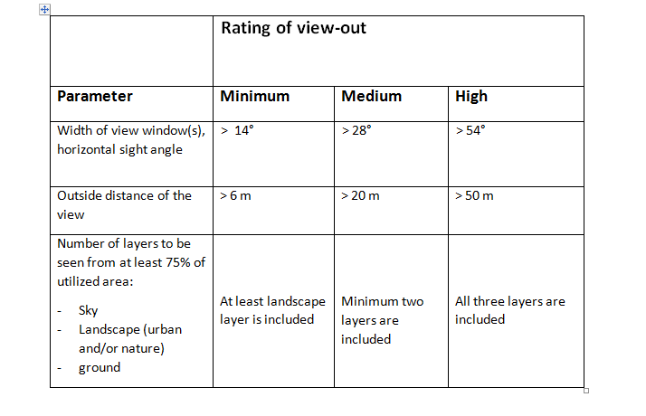
Outside Distance is calculated across the utilized area for each reference point. The rating is done as follow for each reference point:
The averaged distances to the outside obstructions are calculated for each of the three bands (minimum, medium, high) separately. It is the average of all distances to the outside obstructions that fall within a specific radius(correspond to the band). This is considered as valid only if the obstructions within the band obscure the view more than a specified threshold (e.g. 10% threshold in above figure). Otherwise the band is regarded as having no obstructed view and no shortest distance is recorded.
A full sphere fisheye view is rendered for each reference point to accumulate distances on each band from all the openings.
The Settings for View calculation can be set from Project Settings > Assessment Criteria tab:
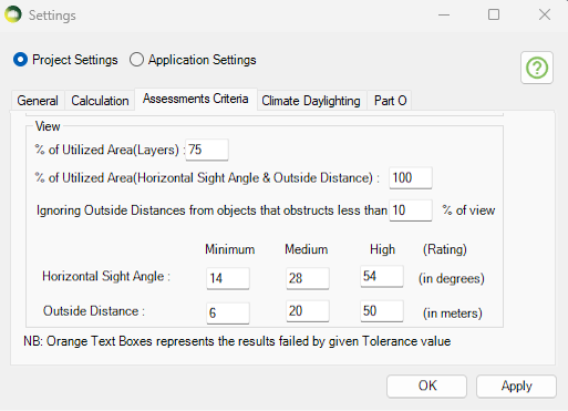
The ViewTest dialog (MBSViewTest command) can be used to visualize the three tests.
The image on the right shows outside distances from a point inside a room. The outside distance is calculated across the utilized area for each reference point. The rating is done as follow for each reference point:
- Distances to landscape layer is used. Distance to Sky and Ground are not used for outside distance to view.
- The average distances to the outside obstructions are calculated for each of the three bands (minimum, medium, high) separately.
- It is the average of all distances to the outside obstructions that fall within a specific radius (correspond to the band).
- This is considered as valid only if the obstructions within the band obscure the view more than a specified threshold (e.g. 10% threshold in above figure). Otherwise the band is regarded as having no obstructed view and no shortest distance is recorded.
- For example, In the image shown, the shortest distance to view is taken from the 0–<6 band as the % of view in that is more than the 10% threshold. If the % of view is less than 10% then the shortest distance will be checked in the 6- < 20 band and so on.
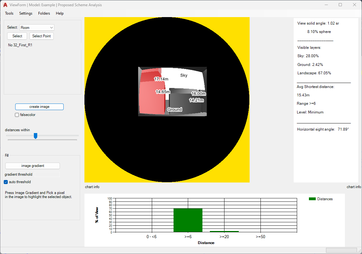
The image on the right shows the falsecolor map for distance to view and other visible layers. Sky, Ground, Inside Room, Beyond lens and various distance band are allocated various colors to distinguish the objects seen from the reference point.
The percentage of visible layers seen (Sky, Ground and Landscape) are shown on the right hand side. The average shortest distance and horizontal sight angle are shown as well.
The chart shows the % of view taken by distance to view in each band.
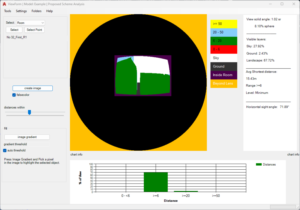
Report FAQs
What are the steps to Preview the results?
- Open preview dialogue (MBSPreview command in AutoCAD).
- Click on the relevant Regulation tab and select the calculation.
- In the Entities Selection section, choose the relevant group or select the entities (Room/Window/Amentity) from the model you are interested in.
- Next, click Preview.
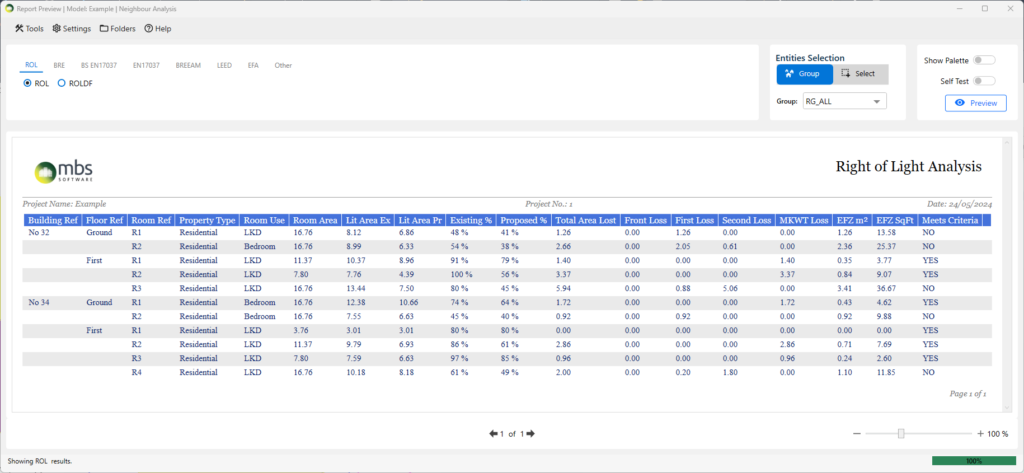
What are the steps to Export the results?
- Open Export dialog (MBSExport command in AutoCAD).
- Click on the relevant regulation.
- Select the tick boxes next to the calculation name to be exported.
- Use a Group from the dropdown or Select entities whose results need to be exported.
- VSC and APSH results are exported in the same sheet for the (default) report and use the VSC group. Bespoke reports may vary.
- Click Export CSV or Export Excel based on your requirements.
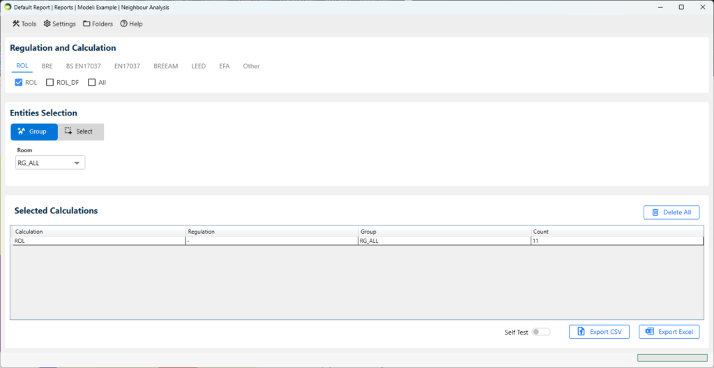
How to use tags from Project Settings in Excel Reports?
- Replaceable tags can be inserted in Excel template including header and footer.
- They should be specified as <tag> e.g. <Project Name> <Report Title>.
- The values can be defined in Project Settings dialog.
Label FAQs
What are the steps to add results to the label?
- Select entity type Window/Room/Amenity
- Tick Existing, Proposed or both options as necessary
- Select the result to be added VSC/APSH/ADF/DD/ROL
- FOR DF and SDA, select one or both Show Median or Show Area % options
- Tick Show Failures option to highlight the failed results with red coloured labels
- Click on Add Labels to add/update labels
Utility Commands
Filter Results
- Analysis Results
- Contour results can be filtered for room based calculations such as DD and DF
- They appear on plan view respective to the level where the rooms exists.
- Facade Results
- Facade results can be filtered for calculations such as VSC, APSH, DD, DF, Amenity and Solar Radiation.
- They are only visible in the 3D view which was active when the calculation was run and on Shaded Visual Style.
- Solids
- Solids results added from the Label dialog can be filtered for calculations such as VSC, APSH, DD and DF
- They are only visible in the default 3D view and on Shaded Visual Style.
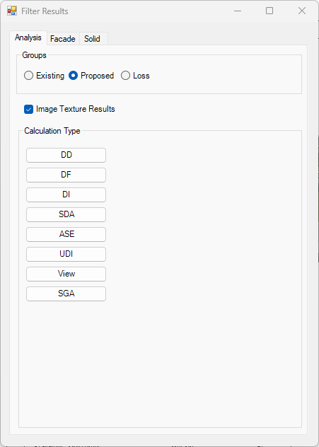
Highlight Registered Windows Not in Groups
- This command can be used to check for windows which are not added to Proposed or Surrounding group for example when they are flagged up when running room calculations.
- The command will highlight all registered windows which are not added to the Proposed or Surrounding group
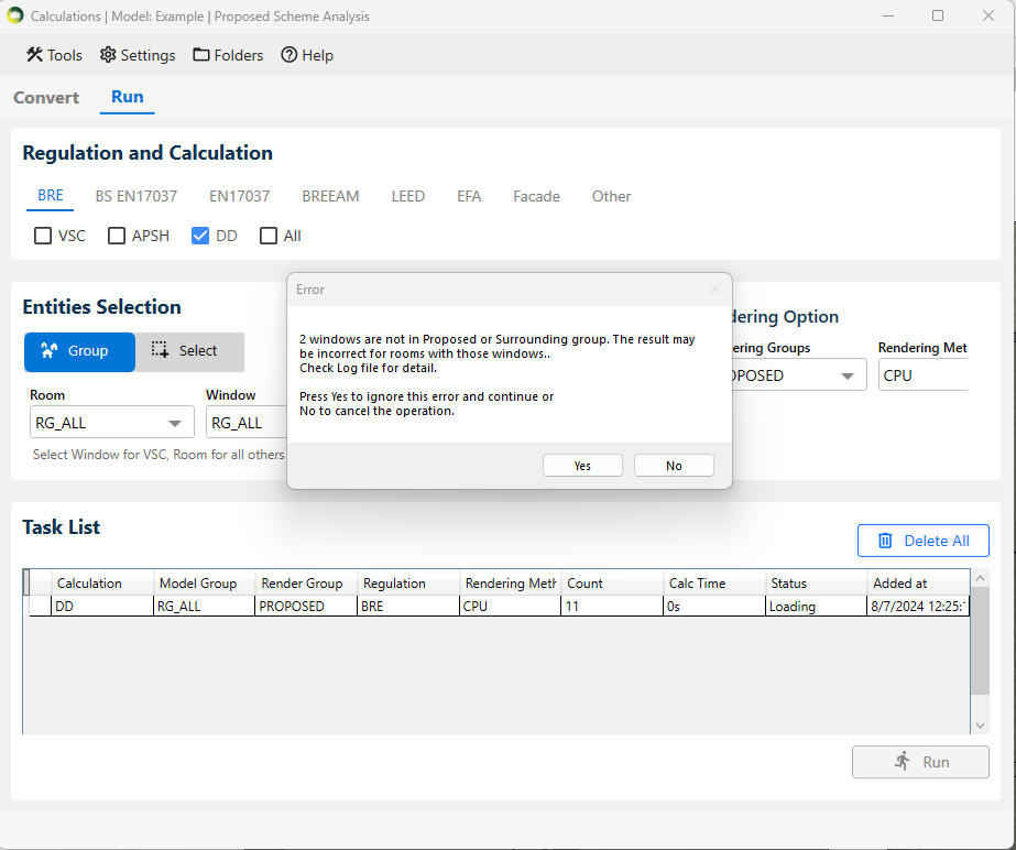
Open Named Host Level floorplan
- This command can be used to open named host level floorplan for a room or a window
- The result tags are view specific are added to the named host level floorplan by default when the results are added from 3D view.
- This can be particularly helpful when there are multiple levels in a similar height and a room can be visible in more than one floorplan but the result tag will only be added to the named floorplan
Window face and ADF glazing faces
- Window face
- This command can be used to check the face whose centre is used as calculation point for VSC and APSH and ADF calculations.
- Window ADF Glazing Faces
- This command can be used to check the glazing faces used for glazed area of ADF calculations.
- The faces are added to the default 3D view.
- Remember to delete them when not needed using Delete Inserted Faces option.
Common Issues
Why am I getting “Cannot modify group” errors?
- The Revit model group doesn’t like if an object within the group is modified without entering the Edit group mode. And Revit API doesn’t provide any simple option to edit the groups in order to modify objects.
- It is highly recommended to avoid putting Windows and Rooms in such groups to avoid errors.
Why are Rooms not visible in the Plan View?
- Visibility/Graphics Override for the Plan view must have Rooms-Reference option ticked for the rooms to be visible.
Why doesn’t the select tool pick a room in the plan view?
- Select element by face option must be un-ticked in the Select option for the Modify for the room selection to work.
Why is the Room separator ignored when trying to modify room shape?
- The room separator must be added to the plan view where room was created.
- Check the Level for the room and open the plan view respective for that Level.