
Installation
What are the steps for installation?
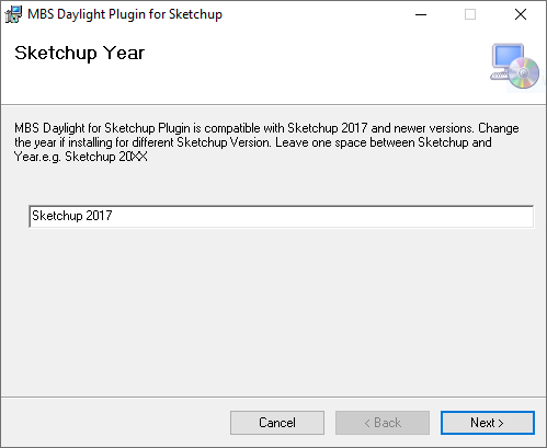
- Right-Click the MBSDaylightForSketchupSetup.exe file and Select Run as administrator.
- Change the Sketchup Year on the textbox as required. Leave exactly one Space between Sketchup and the Year and don’t leave any extra spaces after the year.
- Follow rest of the steps and leave default values for any options.
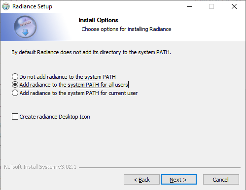
- Remember to Select Add radiance to the system PATH for all users.
What are the steps for updating the software?
- For future updates, follow the below steps
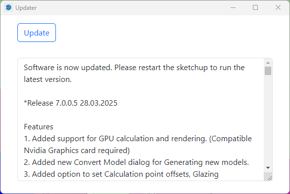
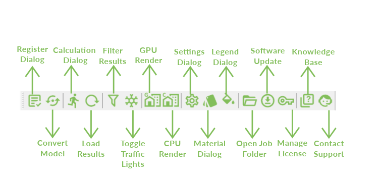
- Open the Software Update dialog by using
the Update plugin icon on the toolbar or
Sketchup Menu > Extentions > MBS Daylight Tool > Update Plugin - Sketchup must be restarted after the update.
- The list of the latest changes will be listed on the dialog.
- Open the Software Update dialog by using
What Sketchup versions is the plugin compatible with?
- The plugin is compatible with Sketchup version 2017 or newer and works on Windows 7 or newer PCs.
Why does the MBS toolbar not appear after installation?
- In some cases, it may remain disabled after installation. Go to View-Toolbars menu and Tick MBS Daylight Toolbar to enable it.
- The commands can also be accessed Extensions – MBS Daylight Tool menu.
- If both options are not visible, Check if the mbsTool extension is disabled on Extension Manager.
Licensing
How to activate the Trial License?
- The Trial license is automatically activated when any of the analysis is run for the first time.
- Groups and registration can be done before the Trial activation.
- The license will be valid for 7 days from the time of activation and gives access to Full features of the Plugin.
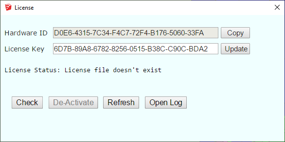
- To manually activate the Trial license or to Check the status
- Click on the Key icon on the MBS toolbar.
- Go to Extensions Menu then MBS Daylight tool then Manage License
- Click Check to activate or check the status.
How to upgrade to the Subscription License?
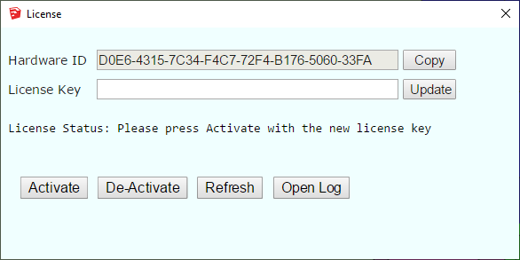
- Once you purchase a Subscription license from MBS, Contact us with the Hardware ID.
- We will provide you with a Subscription version License key.
- Paste the new key to the License Key textbox and Press Update.
- Press Activate. (Internet connection is required).
- The software validates the license regularly with our license server to allow the license to be used on multiple computers.
- Sometimes firewall or anti-virus restrictions can block the license activation and validation. Contact us for details about the license server address which the IT team might need in order to allow the activation.
* The plugin can be installed and used on multiple computers. There is a 30 min cooling off period once the plugin is used on one computer before it can be used on another computer.
How to transfer license to another computer?
- The plugin can be installed and used on multiple computers.
- There is a 30 min cooling off period once the plugin is used on one computer before it can be used on another computer.
- If the plugin needs to be used before the cooling off period, the license needs to be de-activated from the computer where it was last used.
- Once it is de-activated, it can be used on another computer.
Toolbar Menu
Groups
How to name the groups?
- Groups must be named precisely. Existing, Proposed, Surrounding.
- Existing : For buildings/structures which are demolished.
- Proposed : For buildings/structures which are added.
- Surrounding: For buildings/structures which stay the same.
How to group the objects?
- Proposed Scheme doesn’t need Existing group to be present. Analysis type must be changed to Proposed Scheme in Project tab in Settings dialog.
- Extensions to a building.
- If nothing is being demolished and only new extension is being added, then the Existing group can be created with a dummy face on the ground to allow neighbour analysis.
- The Existing, Proposed, Surrounding groups must be the group on top level and not be nested inside any other groups.
How to apply same material on Front and Back face?
It is important to make sure that both front and back face has same material before running calulation in GPU. To apply same material on both face, please follow following steps:
- Open Convert dialog.
- Click on Apply Same material to Front & Back
Registration
Window
How to register individual Window Faces?
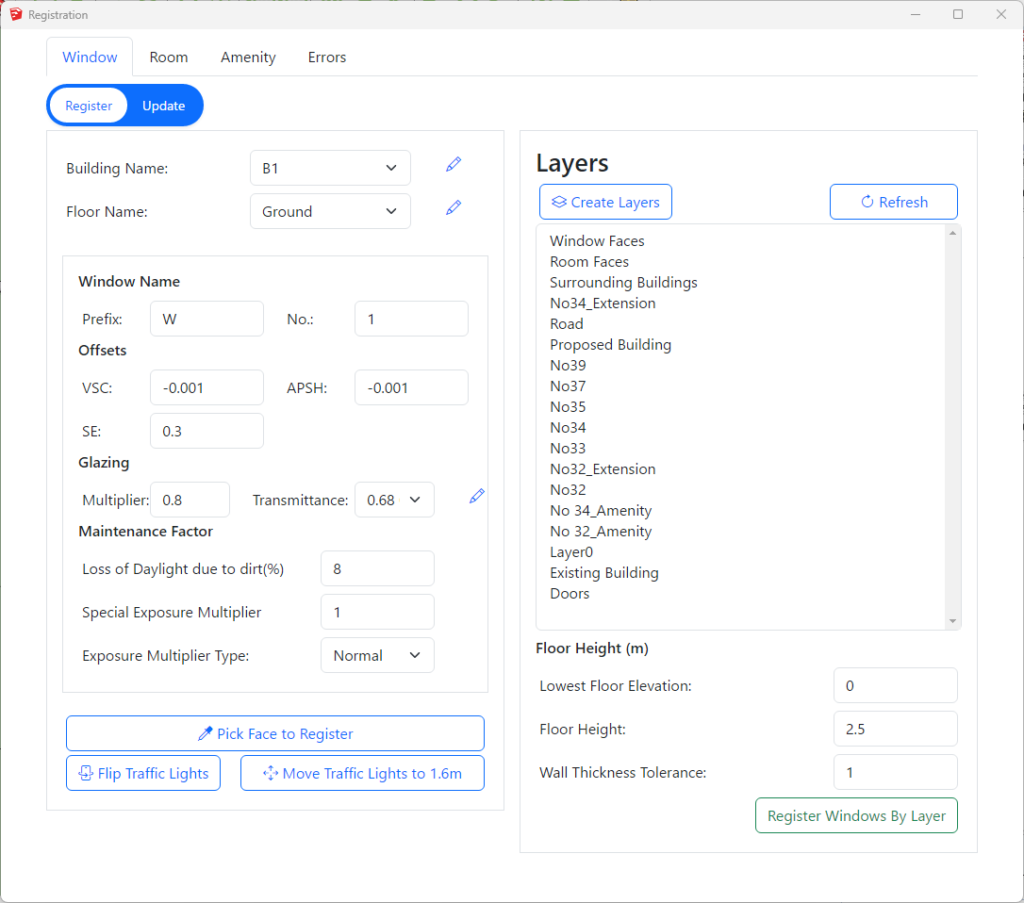
- Open Register Dialog.
- Make sure that you are on Window tab (By default you will be on window tab after you opening the register dialog).
- Then switch to Register mode. (Register button gets highlighted with white background)
- Select an appropriate Building, Floor name and all other parameters in their respective input field. Note: Building name, floor name and transmittance can be added, edited and deleted by clicking on
 icon next to them.
 - Next, click on Pick Face to Register button.
- Hover the mouse over the face which needs to be registered. Click on the face when its highlighted.
- Window number will be automatically incremented by 1. Building, floor name or window number can changed if necessary before registering another face.
- The Traffic Light indicator are added on to indicator layer(tag). If they are not visible, make sure the layer is on.
- Press Esc to end the register process.
How to register multiple Window faces from Layers?
- Open Register Dialog.
- Make sure that you are on Window tab
- Then switch to Register mode.
- Select Building from the lists. These names can be edited by clicking on icons next to them.
- Floor name is detected automatically based on elevation of the centre of the window face.
- Lowest floor is assumed to be on 0 elevation. This can be adjusted on Lowest Floor Elevation text box.
- Default ceiling height is 2.5 m. This is used to decide which floors the faces belong to and can be changed if necessary.
- There must be enough entries for floor names on the list. Otherwise higher windows will be placed on last floor.
- Select one or more layer (tag) names from the list.
- Press the Register Windows By Layer button.
- Window number for faces will be automatically incremented by 1 from the given number.
- The Traffic Light indicator are added on to indicator layer(tag). If they are not visible, make sure the layer is on.
- The Traffic Light indicator is added to the front of the face, so the faces must be oriented correctly. If they are facing inside Flip Traffic Lights can be used to change orientation.
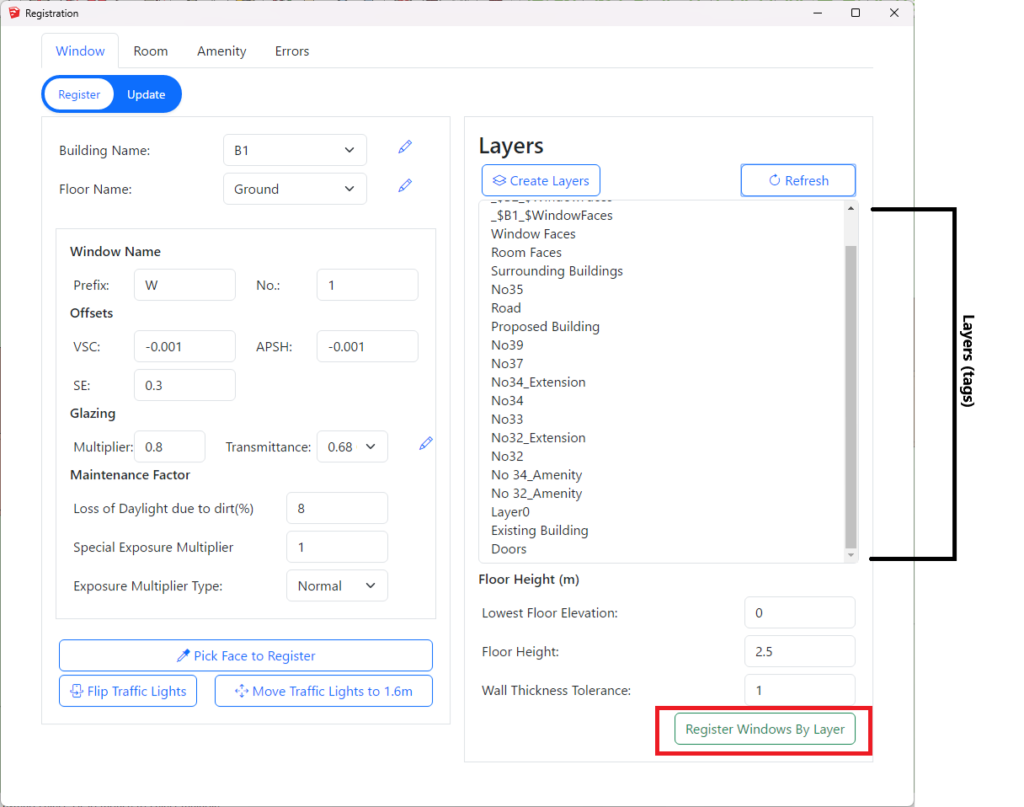
How to specify name of the building on the layer name for layer registration for Window?
Layer name should start with _$ followed by name of the building followed by _$
- For example, Window faces for the building B1 should be in a layer named _$B1_$WindowFaces.
- Open Registration dialog – Window Tab – Register Option has Create Layers button which creates the required layers for window faces for all the building names in the list.
- e.g. _$B1_$WindowFaces, _$B2_$WindowFaces
Room
How to register individual Room faces?
- Open Register Dialog then Click on Room tab and Click on the Register option.
- Select Building, Floor name and fill in other other room properties from their respective input fields. The building name, floor name, room type and property type can be managed by clicking on icon next to them.
- Click the Pick Face to Register button.
- Hover the mouse over the face which needs to be registered. Click on the face when its highlighted.
- Room number will be automatically incremented by 1. Building, floor name or room number can changed if necessary before registering another face.
- The room label are added to Room_Names layer(tag). If they are not visible, turn on the layer.
- Press Esc to end the register process.
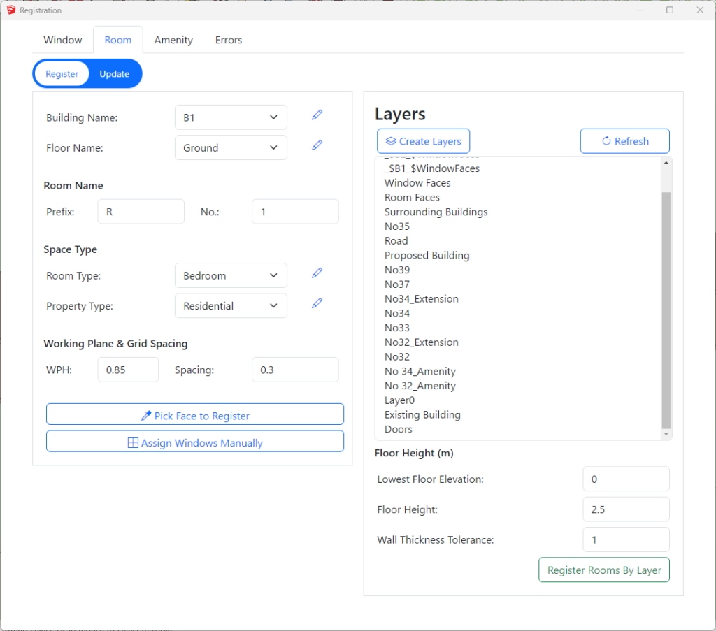
How to register multiple Room faces from Layers?
- Open Register Dialog then Click on Room tab then Click on the Register option.
- Select Building from the lists. The names can be edited by clicking on icon next to them.
- Floor name is detected automatically based on elevation of the room face.
- Lowest floor is assumed to be on 0 elevation. This can be adjusted on Lowest Floor Elevation text box.
- Default ceiling height is 2.5 m. This is used to decide which floors the faces belong to and can be changed if necessary.
- There must be enough entries for floor names on the list. Otherwise higher rooms will be placed on last floor.
- Select one or more layer (tag) names from the list.
- Press the Register Rooms By Layer button.
- Room number for faces will be automatically incremented by 1 from the given number.
- Room labels are added on to Room_Names layer. If they are not visible, make sure the layer is on.
How to specify name of the building on the layer name for layer registration for Room?
Layer name should start with _$ followed by name of the building followed by _$
- Room faces for the building B1 should be in a layer named _$B1_$RoomFaces.
- Room layers can also have room type and required adf at the end. So Bedrooms in B1 should be in layer named _$B1_$Bedroom_$1
- Open Registration dialog -> Room Tab -> Register Option has icon next to the room type dropdown list which opens the room types dialog.
- Select the room types from the table and Press Create Layers button to create the required layers for room faces for all the building names in the list for the selected room types.
- e.g. _$B1_$Bedroom_$1, _$B2_$Bedroom_$1
- If no room type is selected when pressing the Create Layers button, layers will be created without any room types.
- e.g. _$B1_$RoomFaces, _$B2_$RoomFaces
- Open Registration dialog -> Room Tab -> Register Option has
How to specify room type and required ADF value on the layer name for ADF calculation?
- Layer name should end with _$ followed by RoomType followed by _$ followed by Required ADF.
- The layer name can include room type info along with the building name.
- For example, Room faces for Bedrooms in B1 should be in layer named _$B1_$RoomFaces_$Bedroom_$1
- If building name is not included in the layer name, layer should be named RoomFaces_$Bedroom_$1
- To create the layers automatically Open Registration dialog – Room Tab – Register Option has icon next to Room Types dropdown option which opens the room types dialog.
- Select the room types from the table and Press Create Layers button to create the required layers for room faces for all the building names in the list for the selected room types.
- e.g. _$B1_$Bedroom_$1, _$B2_$Bedroom_$1
Amenity
How to register individual Amenity faces?
- Open Register Dialog then Click on Amenity tab then Click on the Register option.
- Select Building and Floor name from the lists. The names can be edited by clicking on icon next to them.
- Press the Pick Face to Register button.
- Hover the mouse over the face which needs to be registered. Click on the face when its highlighted.
- Amenity number will be automatically incremented by 1. Building, floor name or amenity number can changed if necessary before registering another face.
- The amenity label are added to Amenity _Names layer(tag). If they are not visible, turn on the layer.
- Press Esc to end the register process.
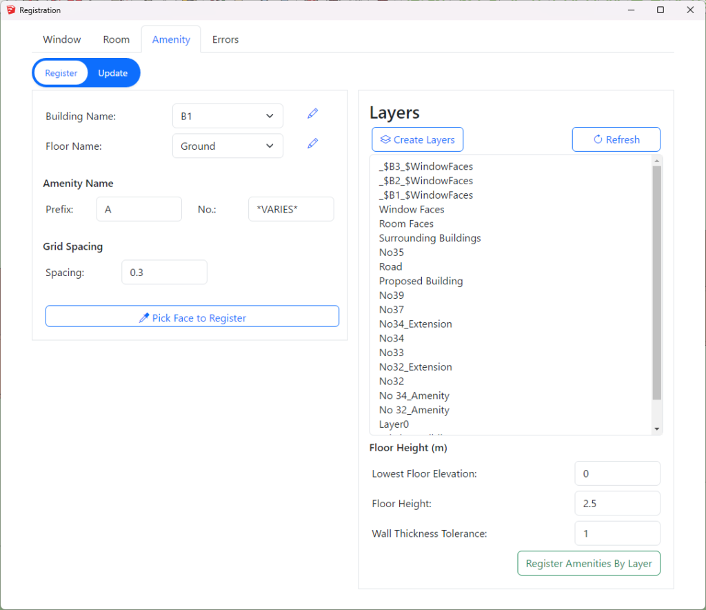
How to register multiple Amenity faces from Layers?
- Open Register Dialog then Click on Amenity tab then Click on the Register option.
- Select Building from the lists. The names can be edited by clicking on icon next to them.
- Floor name is detected automatically based on elevation of the amenity face.
- Lowest floor is assumed to be on 0 elevation. This can be adjusted on Lowest Floor Elevation text box.
- Default ceiling height is 2.5 m. This is used to decide which floors the faces belong to and can be changed if necessary.
- There must be enough entries for floor names on the list. Otherwise higher amenities will be placed on last floor.
- Select one or more layer (tag) names from the list.
- Press the Register Amenities By Layer button.
- Amenity number for faces will be automatically incremented by 1 from the given number.
- Amenity labels are added on to Amenity_Names layer. If they are not visible, make sure the layer is on.
How to specify name of the building on the layer name for layer registration for Amenity?
Layer name should start with _$ followed by name of the building followed by _$
- Amenity faces for the building B1 should be in a layer named _$B1_$AmenityFaces.
Modify
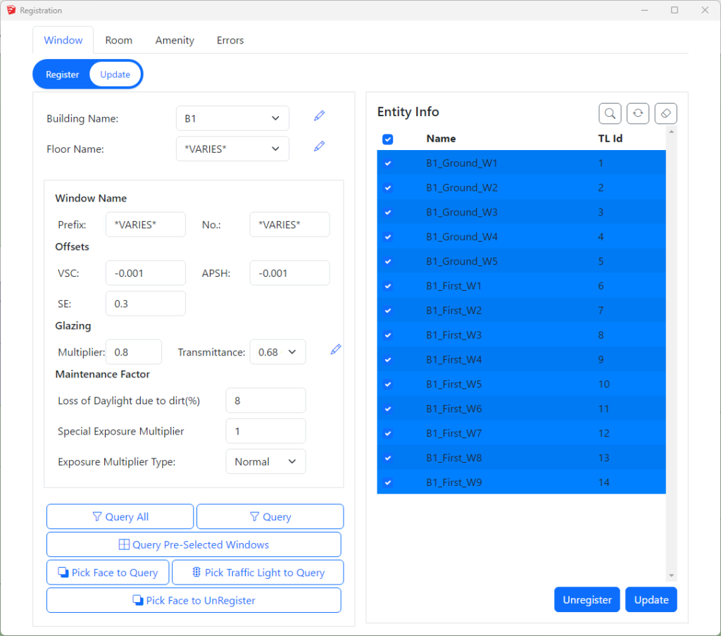
How to query registered Windows/Rooms/Amenities?
In Sketchup, there are few ways to query the registered entities. These options are available on update mode in registration dialog for each entity type (Register Dialog -> (Window/Room/Amenity) -> Update).
Query All
- Query All option is used to query all the registerd entities available.
- Open Register Dialog then Click on Window/Room/Amenity tab then Click on the Update option.
- Press the Query All button.
- All the registered entities will be listed on the table.
Query
- Query option can be used to fetch subset of registered entities based on the selected parameters in the form.
- Building Name, Floor Name, Entity Name prefix and entity number options can be used to filter the query.
- Select the appropriate value for above mentioned option as per your requirement. To ignore the certain option select either All or *VARIES*. Note: you can put *VARIES* in prefix text field to ignore the filter by prefix.
- Then click on the Query button.
Query Single Face
- Press the Pick Face to Query button.
- Click on the face. If the face is registered correctly, it will be added to the list.
Query Faces pre-selected in Sketchup
- Press the Query Selected Windows/Rooms/Amenities button.
- All registered entities will be added to the list.
- It can be face or the traffic light for windows.
How to unregister registered Windows/Rooms/Amenities?
- UnRegister Everything
- Open Register Dialog then Click on Window/Room/Amenity tab.
- Then Click on the Update option.
- Press the Query All button.
- All the registered entities will be listed on the table.
- Select the entities (Windows/Rooms/Amenities) from the list you want to unregister.
- Click on Unregister button.
- UnRegister Single Face
- Press the Pick Face to UnRegister button.
- Click on the face. If the face is registered correctly, it will be unregistered.
- For windows, traffic lights cannot be clicked for unregistering.
- UnRegister listed entities
- To unregister the entities listed in table on right hand side of dialog box, you need to select the items.
- To select the single item simply click on it. If you want to select multiple items click on items with Ctrl key pressed or you can simply click on the box on the left side of the list.
- Similarly, to select the all items in the list, click on the box in heading section adjacent to Name.
- After selecting the items to be unregistered. Click on Unregister button.
How to renumber registered Windows/Rooms/Amenities?
- Renumber selected entities
- Open Register Dialog then Click on Window/Room/Amenity tab.
- Then Click on the Update option.
- Query the entities to be renumbered and select them.
- Add the number in No. option to be numbered from. For example, if you want to renumber B1_Ground_W3 and B1_Ground_W4 to B1_Ground_W5 and B1_Ground_W6 insert 5 in No. option.
- Click on
 icon which is located at top right of the table.
How to update building/floor names of registered Windows/Rooms/Amenities?
- Rename the building or floor name.
- The names can be edited by clicking on icon next to them.
- Edit the names and Save Names
- The window/room/amenity labels are automatically changed.
- The names can be edited by clicking on
- Update building name (Move registered entity to another building)
- Open Register Dialog then Click on Window/Room/Amenity tab then Click on the Update option.
- Query the entities to be updated.
- Select Building name from the list. The names can be edited by clicking on icon next to them.
- Change the Building name.
- Then click on Update button.
- Update floor name (Move registered entity to another floor)
- Open Register Dialog then Click on Window/Room/Amenity tab then Click on the Update option.
- Query the entities to be updated.
- Select Floor from the lists. The names can be edited by clicking on icon next to them.
- Change the Floor name.
- Then click on Updated button.
- The window/room/amenity labels are automatically changed.
Registration FAQs
How do I modify Glass Transmittance value?
To modify the Glass Transmittance value in registered window, please follow the following steps:
- Open the register dialog and switch to update mode. Make sure you are in window tab.
- Query the window(s) that need to be updated.
- Select the suitable Transmittance value from the Transmittance option that is available in Glazing section.
- If the transmittance value that is required to be used is not available in list, then it can be easily added by clicking icon next to the dropdown option.
- The similar option can be used to update and delete the exisiting Transmittance option.
- Please, make sure to click update button to save the changes you have made.
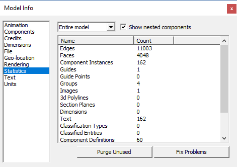
How do I reset my Traffic Light IDs to start at 1?
- First you will need to delete all the current window markers
- Select “Window” then “Model info” from the menu then Statistics
- Finally click on “Purge Unused”
Material Settings
About Material Dialogue
Material Dialogue can be opened by clicking on the ![]() icon on the tool bar.
icon on the tool bar.
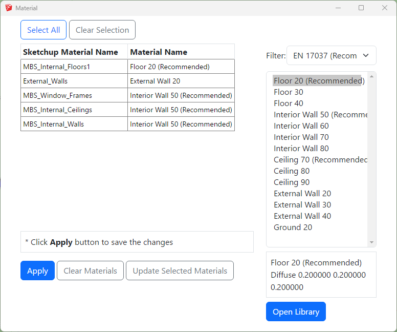
The material table is empty for a new project. The list is populated with the materials based on the Sketchup Material value when the model is converted for the first time. It an then be modified WITHOUT a need to re-convert the model. Therefore this gives more flexibility on experimenting different materials and parameters for an analysis.
How to prepare a model for Assigning the Materials?
Put objects in the model to their corresponding layers. Normally for indoor calculations like Climate or Daylight Factor the scene is divided into two groups of objects, external obstructions and room internal surfaces.
and What happens to registered Windows Glazing Transmittance?
In AutoCAD, separating floors, walls and ceilings objects and put them in their layers (e.g. all walls objects to “wall” layer) can be a challenge.
Any solid object has to be exploded first to access the individual surfaces. Care must be taken to put back the exploded objects back into their original ClassicGroup.
Updating Material
Updating the MBS Material for Sketchup Material
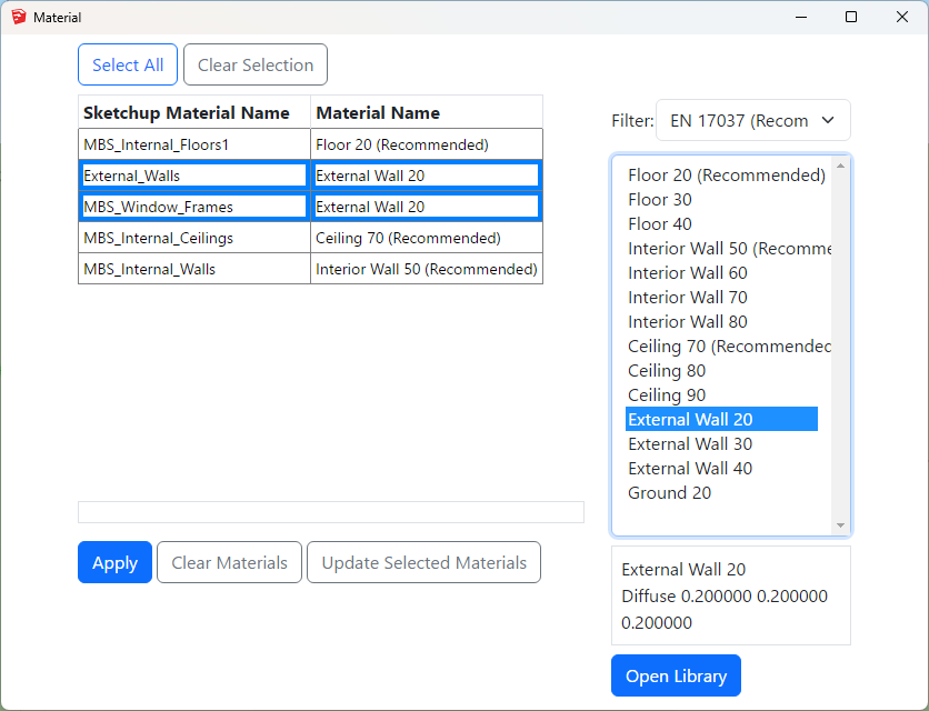
- Select one or more rows from the Sketchup Material Name – Material Name list on the left hand side for which you want to update the material.
- Select the desired material from the Material list on the right hand side.
- Then click on Update Selected Materials button.
- Repeat steps 1 – 3 as necessary.
- Press Apply and Close the dialog.
- Updating the materials this way doesn’t require model reconversion
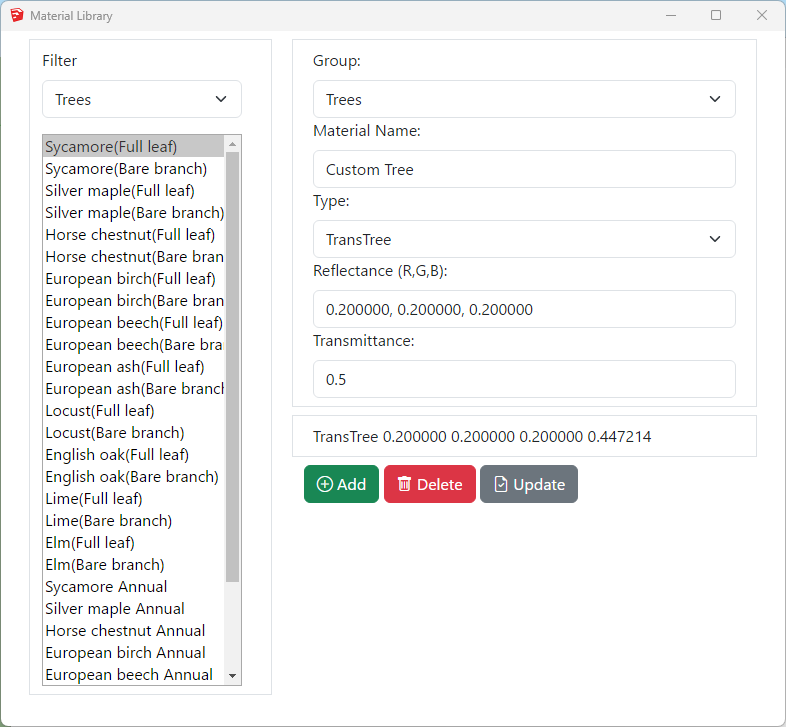
Adding New Material
Adding New Material to the library
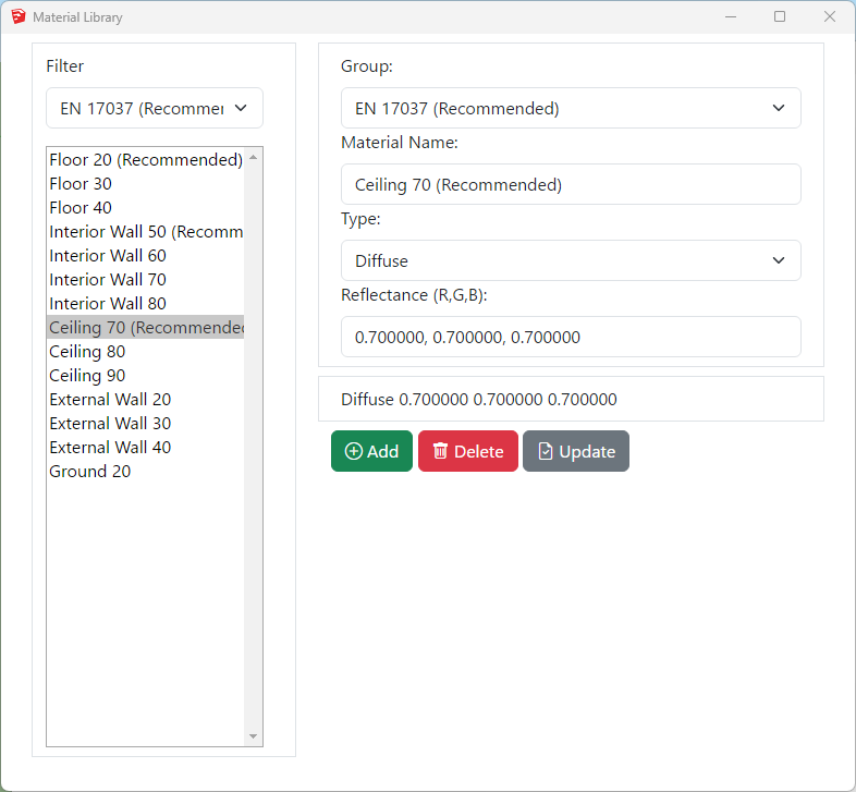
- Click on the Open Library button
- Select a existing Group or Type a new group name for the material on the Group combo box.
- Type a unique name on the material name text box.
- Select a Material Type from the Type combo box. See below for detail on types.
- Assign material properties on the relevant text boxes.
- Press Add and Close this dialogue.
- Remember to Press Apply on the Material dialogue.
- Diffuse surface reflects light uniformly over the entire reflecting hemisphere. A Lambertian (or diffuse) surface appears equally bright from all viewing directions.
The reflectance parameter represents the fraction of the incident energy that is reflected at a surface. The parameter has three components which range from 0 to 1. - Mirror (specular reflection) surface only reflects light in one specific direction.
- ThinGlass is a special case of dielectric, infinitely thin and therefore does not change the transmitted ray direction. It is modelled as a single surface. The default refractive index is 1.52.
Transmittance is the ratio of the total transmitted light to the incident light which includes multiple inter-reflections in a layer of glass.
The parameter is a single value from 0 to 1 – Reflectance field is disabled as it is a function of angle, refractive index of the material and transmissivity.
Transmissivity applies to a single pass of light through a layer of glass and excludes multiple interreflections within the medium.
ThinGlass is translated to Radiance glass material. Transmittance value is converted to transmissivity for the Radiance rad file. - TransTree is a mix of Diffuse Reflection (representing leaves) and Specular Transmission(the gaps). See How to assign the Materials for Trees? for more details.
- Translucent material is a mix of diffuse reflectance/transmittance and perfect/glossy specular reflectance and transmittance. It describes diffuse and glossy specular reflection and transmission through the surface.
Translucent parameters are well described in this link: http://www.schorsch.com/en/software/rayfront/manual/transdef.html - BSDFRadiance material, only valid on Radiance method, is to define material for complex glazing system.
The input is an xml file containing BSDF matrix data. This file can be generated using WINDOW 6.0 BERKELEY LAB application.
Please follow instruction on BSDF Files for Radiance Renderings page.
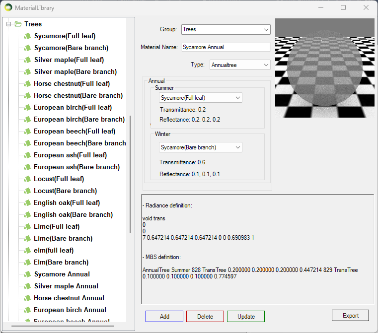
How to assign the Material for Trees?
Assign Tree Material from pre-defined BRE trees
TransTree is a mix of Diffuse Reflection (representing leaves) and Specular Transmission (the gaps). This material is suitable for simulating trees on BRE (ADF, VSC, APSH, Amenity) or Daylight Factor calculations. The Reflectance value on ADF, VSC, APSH, Amenity calculations only reflects in terms of the colour as no reflected light is accounted for. The Transmittance value is the overall transparency of tree crown as the ray enters and exists the tree volume. Follow the below steps to assign tree material to a layer:
- Put the tree objects with the same transparency to a layer.
- Then Open the Materials dialogue and assign one of the predefined BRE tree materials.
- The trees mentioned BRE Site Layout for Daylight & Sunlight Appendix H Table H1 are included in the material library.
*For SDA calculations please refer to https://www.mbs-software-uk.com/knowledge/sda-calculation-with-trees/
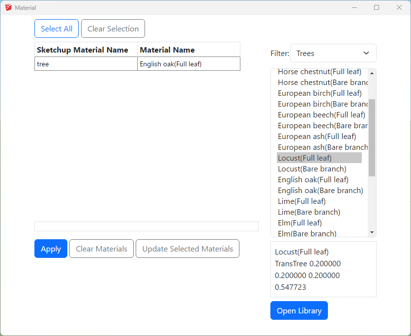
Creating a custom Tree material
- Open Material dialog then Press Open Library button.
- Create a new TransTree type material.
- The reflectance values are used during DF calculation only. It is used for the colour of the tree in case of VSC, APSH, ADF and Amenity calculations.
- The transmittance is converted automatically to consider the overall transparency of the tree crown as the ray enters and exits the tree volume.
- For example 50% overall transparency should be input as 0.5 which will then be converted to 0.707 (√0.5) to adjust for the ray entering and leaving the tree crown. This can also be seen on material preview area.
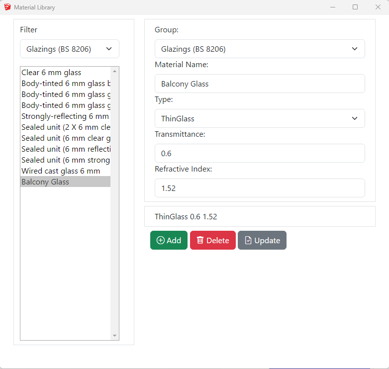
How to assign the Materials for Balconies?
- Balconies are supported for all calculations including Ray-traced based (Daylight Factor and Climate) and BRE (VSC, APSH and ADF).
- Put the balcony objects with the same transparency to a layer.
- Objects with single face should be used.
- Using objects with multiple faces may result in the transparency being applied multiple times.
- If the overall transparency of the balcony modelled as solid is 0.60,
- Then the ThinGlass transparency should be √0.60 i.e. 0.775
- Open Material dialogue then Press Open Library button
- Create a new ThinGlass type material
- The normal transmittance value should be in put as unit value e.g. 0.6 for 60%
- Refractive index of 1.52 is define as default.
- Press Add and Close this dialog.
- Remember to Press Apply on the Material dialogue.
- Then Assign the material to the layer with balcony objects on the Materials tab.
Refer to Updating Material For Layer topic for details.
Legend Settings
Gradient Legend
Gradient legend has four different colour options. Intermediate colours are added to avoid colour contrast between values between two intervals. The breakdown of intermediate colours is as below:
- Two colour: 2 for the min and max colours and 19 interpolated colours field between them.
- Three colour: 3 for the given colours and 9 interpolated colours field is applied between first and second and second and third colour.
- Rainbow colour: 7 for the given colours and 18 for the intermediate colours between them. (give value from interpolated colours field between each consecutive colour except the last one)
- Default colour: 11 for the given colours and 10 for the mid colour between them except the last one.
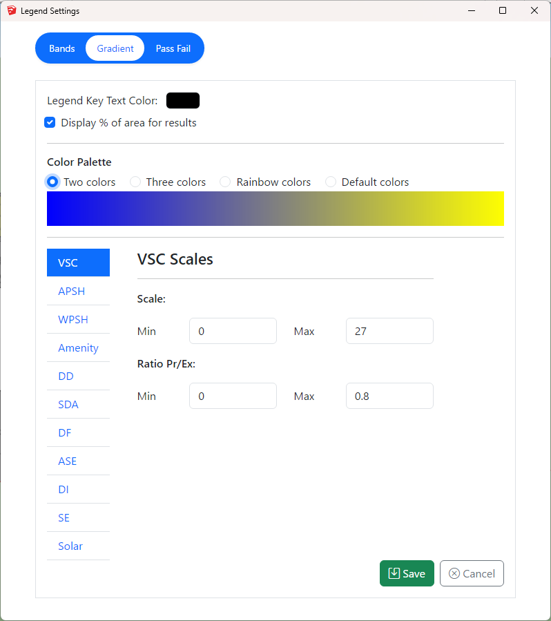
Legend interval
The interval for legend values is created by dividing the min and max values equally to the legend colours. Interval values for legend colours are calculated using the formula (Max value – Min value) / (total colours in legend – 1). The last colour is for all values greater than max therefore (total colours – 1) is used.
For example, The interval of values per Default legend colour for VSC legend with min of 0 and max of 27 will be calculated as below.
(27-0) / (21-1) = 1.35
Gradient Legend is supported by the following calculations
Facade
- VSC, APSH, SE, Amenity and Solar Radiation
Solids
- VSC, APSH, SE, DF
Result Images
- All room calculation types.
- ROL, DD and Amenity use these colours when Use Image Texture for Room/Amenity Results option in Application Settings is ticked.

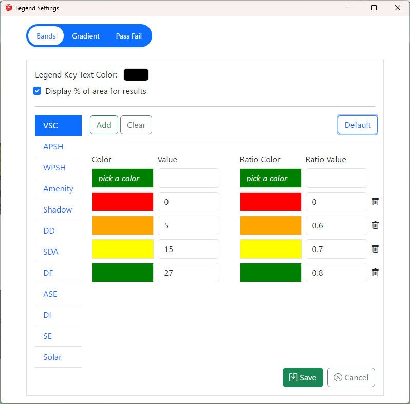
Band Legend (Non-Gradient)
- Select the calculation type on the sidebar menu to define a band legend values.
- Then choose a colour and enter a value. The values must be in ascending order.
- The first value will be the minimum value and last value will be maximum value for any calculation.
Band Legend is supported by the following calculations
Facade
- VSC, APSH, SE, Amenity, DF and Solar Radiation
Solids
- VSC, APSH, SE, DF
- Pass Fail legend will be used for calculation which don’t support band mode.
Result Images
- All room calculation types.
- ROL, DD and Amenity use these colours when Use Image Texture for Room/Amenity Results option in Application Settings is ticked.
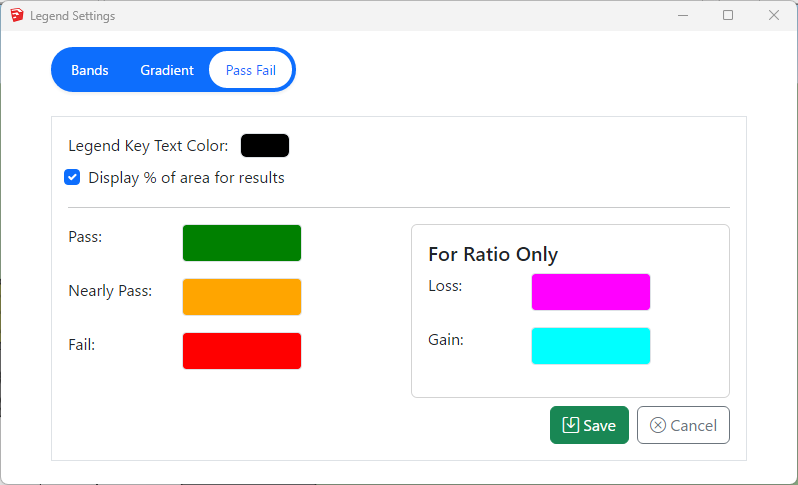
Pass Fail Legend
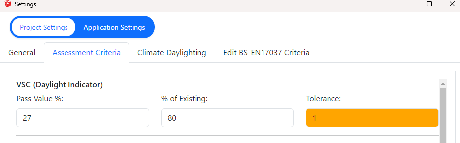
The legend will be created with just three colours for Pass, Nearly Pass and Fail. The colours can be changed by the users. The pass values for VSC and APSH is taken from Project settings Assessment criteria section.
For Example, for VSC calculation
- if the result >= 27 (or) loss < 20 % then it passes
- if the result >= 26 (or) loss < 21 % (Tolerance = 1) the it is Nearly Passed
- otherwise it will fail.
- The legend will show Pass, Nearly Pass and Fail results.
- If the calculation is run for neighbour scheme only one legend is created.
Pass Fail Legend is supported by the following calculations only
Facade
- VSC, APSH, SE and Amenity
- Band legend will be used for DF and Solar Radiation if Pass Fail legend is set
Solids
- ROL, DD, VSC, APSH, Amenity, SE and DF
Result Images
- None
- Band legend will be used if Pass Fail legend is set
Neighbour Analysis
Neighbour Analysis
Sunlight To Amenity
Neighbour Analysis FAQs
How do I fix Group could not be loaded error?
- Check the Group names are correct.
- Check the Groups are not hidden on Outliner.
- Make sure the Groups exist according to the Analysis Type on Project Tab on Settings.
- Neighbour Analysis requires both Existing and Proposed groups.
- Proposed Scheme Analysis requires Proposed group.
- If the model consists of Proposed Scheme only, Change the Analysis Type to Proposed Scheme on Project Tab on Settings.
Can I run multiple calculations?
Yes. Open the calculation dialog. Select a test from the options and press Add to List. Repeat this for other calculations you want to run.
They will be grouped and sent to the service all together. Separate reports will be created for each unique calculation.
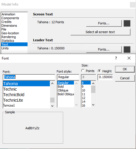
How can I change the height of the result texts?
- Select “Window” then “Model info” from the menu then “Text”
- Finally click on Fonts Button on Leader Text Section
- The text scale better on the Size by Height option
- The results texts will change after the calculation is re-run
Why are the result texts coming too wide/far from?
- Open Settings dialog
- Go to Settings dialogue -> Application Settings -> Calculation.
- Change Text Offset value from the Text Offset option.
The value should be entered in meters regardless of the unit used in the model.
The contour image does not look correct or match the texture image
If the contour image does not match the texture image from the model:
- Face style must be Shaded With Textures.
- Go to View Menu on Sketchup Menubar then Click on Face Style and Select Shaded With Textures.
How can I change the criteria for different assessments?
- To set the criteria for VSC, APSH and Amenity, Open the settings dialogue > Project Settings > Assessment Criteria.
- DD criteria cannot be changed.
Can I move the VSC/APSH test sensor location?
- Open the Register dialogue -> Window.
- Go to Offsets section and set offset values.
- The offset values will be applied in the direction of the face orientation.
How does the software detect North direction?
- The North direction is taken based on the Sketchup’s cardinal direction.
- Solid Green line is treated as North
- Dotted Green line is treated as South
- Solid Red line is treated as East
- Dotted Red line is treated as West
- Refer https://help.sketchup.com/en/sketchup/adjusting-drawing-axes for details.
Why do all the traffic light icons look same color after running calculations?
- The “Color by layer” may have been ticked.
- Untick the option on Layers Tray then Details (Small arrow on the right side of the tray)
How can I set room types for DD and ADF calculations?
- The room type used for ADF or DD calculation is either taken from the room layer name or the “Room Type” selected during registration of room from registration dialog.
The room type from the layer name is used if defined otherwise the value from the room type list is used.
To set room type by layer: The layer name must be in a specific format : LayerName_$RoomType_$ReqValue e.g. LayerName_$Bedroom_$1.5
You can use the room type dialogue to create all the required layers in correct format. For this follow the following procedure:- Step 1: Open the registration dialogue.
- Step 2: Go to room tab.
- Step 3: Click on the “” icon next to Room Type option, the room type dialogue will appear.
- Step 4: Tick the room types that you want to create the template layers for them and click on “Create Layers” button to create layer in the expected format.
In-order to update/change the “Room Type”:
- Step 1: Open the registration dialogue.
- Step 2: Go to room tab and select Update option.
- Step 3: Query and select the rooms you want to update from entity info table. (Ctrl + click or tick on box for multiple selection.)
- Step 4: Select the desired Room Type from the dropdown list in Space Type section.
- Step 5: Finally, click on Update button to execute update room type command.
How do I change the density of the sensor points on DD calculation?
To change the Grid Spacing follow the following procedure:
- Step 1: Open register dialog from Menu.
- Step 2: Navigate to Room tab.
- Step 3: Go to Working Plane & Grid Spacing section.
- Step 4: There you will find Grid Spacing textbox.
Can I change the DD/NSL result image colors ?
Yes.
The colors can be changed in the Legend Settings.
Where can I set Glazing Transmittance for ADF test?
To set the Glazing Transmittance for ADF test follow the following steps:
- Step 1: Open the Register dialog from menu.
- Step 2: Navigate to Window tab within register dialog.
- Step 3: Go to Glazing section.
- Step 4: There you will find Transmittance option, update the value.
All other ADF parameters must be updated from Settings. For this:
- Open Setting Dialog.
- Switch to Application Settings.
- And Go to Room Properties.
What do the DD/NSL result image colours represent?
- Existing/Proposed Contour
- The legend color image is saved as DD_.png file on Images/RoomLegend folder in the job folder.
- Ratio Contour
- The legend color image is saved as DD_Ratio.png file on Images/RoomLegend folder in the job folder.
Is it possible to change the DD threshold factor to match the ROL analysis criterion?
No. Although same sky type and methodology is used on calculating NSL test, the threshold cannot be changed for DD to match the ROL test.
What do the Amenity result image colours represent?
Legend values set in the Legend Settings for Amenity are used on the contour images.
- Existing/Proposed Contour
- The legend color image is saved as AMENITY_.png file on Images/RoomLegend folder in the job folder.
- Ratio Contour
- The legend color image is saved as AMENITY_Ratio.png file on Images/RoomLegend folder in the job folder.
Where can I set a different location for Amenity or APSH test?
To set different location for Amenity/APSH test follow the following steps:
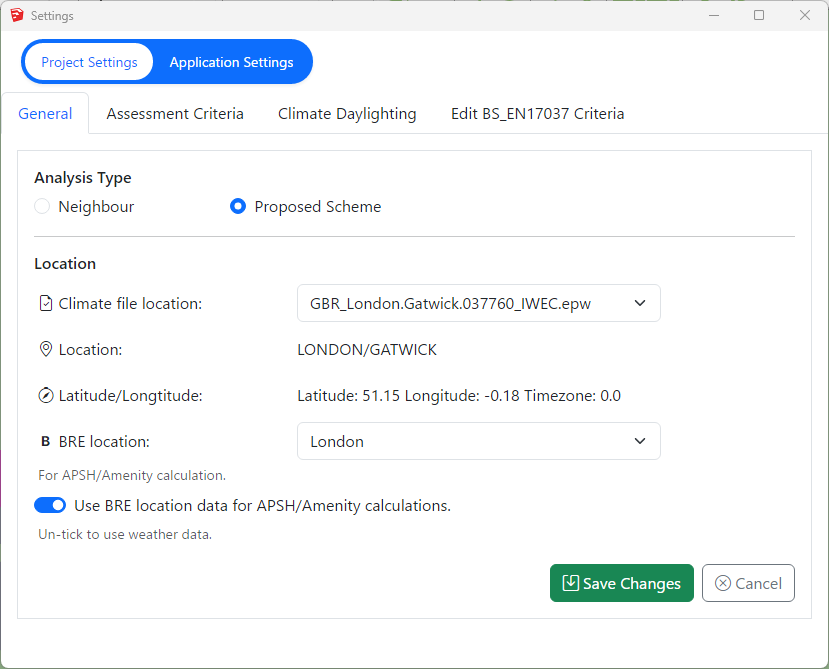
- Step 1: Open the Settings dialog from Menu.
- Step 2: Navigate to Project Setting. (By default you will be in Project setting Section. Make sure that the Project Settings tab on top is highlighted in white color.)
- Step 3: Click on general tab. (By default general tab is opened. Make sure that the general tab is highlighted with blue text.)
- Step 4: Adjust the Climate file location settings accordingly.
Note: Make sure to untick “Use BRE location data for APSH/Amenity calculations”.
You can add new climate data file by placing the weather file in below folder:
%appdata%\MBS Software\DaylightForSketchup\Climate Files
Daylight Factor and SDA Calculations
Daylight Factor
BREEAM Daylight Factor Criteria
Terms and Definitions
Average Daylight Factor
The average daylight factor is the average indoor illuminance (from daylight) on the working plane within a room,
expressed as a percentage of the simultaneous outdoor illuminance on a horizontal plane under an unobstructed CIE Standard Overcast Sky.
Point Daylight Factor
A point daylight factor is the ratio between the illuminance (from daylight) at a specific point on the working plane within a room, expressed as a percentage of the illuminance received on an outdoor unobstructed horizontal plane. The minimum point daylight factor is the lowest value of the daylight factor on the working plane at a point that is not within 0.5m of a wall.
Uniformity
The uniformity is the ratio between the minimum illuminance (from daylight) on the working plane within a room (or minimum daylight factor) and the average illuminance (from daylight) on the same working plane (or average daylight factor).
Daylight Factor Criteria
BREEAM 2018
The relevant building areas must meet
1. Minimum value of average daylight factors required
2. Daylighting uniformity criteria
BS EN17037 Daylight Factor Criteria
Daylight Factor Criteria
UK National Annex
The UK Annex is intended for “hard to light” dwellings.
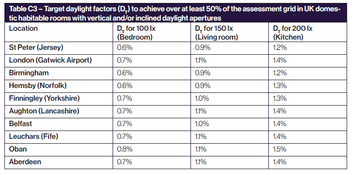
The targets for DF is linked to the lux targets defined for BS EN17037 SDA (This can be accessed via Project Settings Climate Daylighting tab). The target DF is calculated based on the target illuminance and the median external diffuse illuminance. e.g. For London Gatwick, median illuminance is 14100. The equivalent target DF for 100 lux is (100 / 14100) % 100 % i.e. 0.7%
The target DF is to be met for 50% of the time over 50% of the space
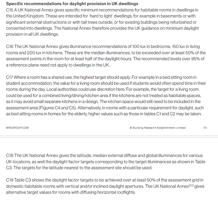
EN17037 Daylight Factor Criteria
Daylight Factor Criteria
The targets for DF is linked to the lux targets defined for EN17037 SDA. (This can be accessed via Project Settings Climate Daylighting tab). The target DF is calculated based on the target illuminance and the median external diffuse illuminance. e.g. For London Gatwick, median illuminance is 14100. The equivalent target DF for 300 lux is (300 / 14100) % 100 % i.e. 2.1%
The target DF is to be met for 50% of the time over 50% of the space. The min target DF is to be met for 50% of the time over 95% of the space.
Setting Pass Criteria
Assessment Criteria are set per project. To set the criteria follow the following steps:
- Open Setting dialogue
- Project Settings dialogue
- Climate Daylighting tab.
- Click on one of the Regulations in climate daylighting tab. It will open the relevant edit criteria form in next to climate daylighting tab.
DF BS EN17037 Criteria
The criteria is set according to BS EN17037 regulation. The DF criteria are derived from the SDA criteria based on the room type and the Median diffuse horizontal illuminance for the location.
For e.g. Median diffuse horizontal illuminance for London Gatwick based on the energy plus epw file is 14100. So the equivalent DF target for Living Room will be (150/14100)*100 = 1.1
DF EN17037 Criteria
The criteria is set according to EN17037 regulation. The DF criteria are derived from the SDA criteria based on the selected space type targets and the Median diffuse horizontal illuminance for the location.
For e.g. Median diffuse horizontal illuminance for London Gatwick based on the energy plus epw file is 14100. So the equivalent DF target for 300 Lux will be (300/14100)*100 = 2.1

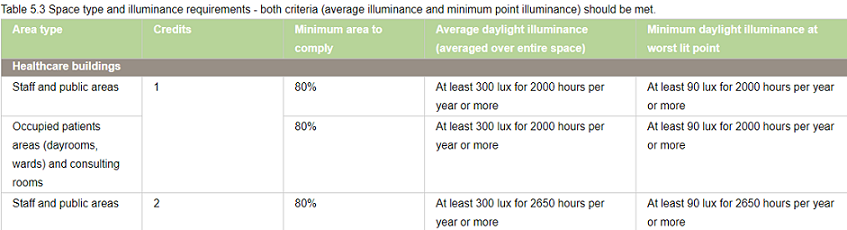
BREEAM DF Criteria
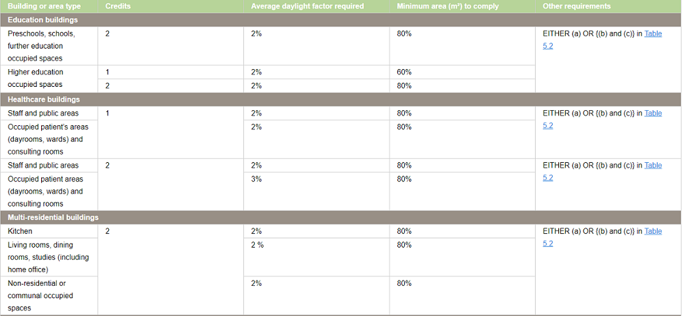
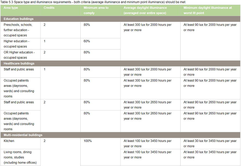
All the entries on BREEAM Regulations Table 5.1 are predefined based on the BREEAM New Construction 2018 and loaded as default in Criteria table dialogue.
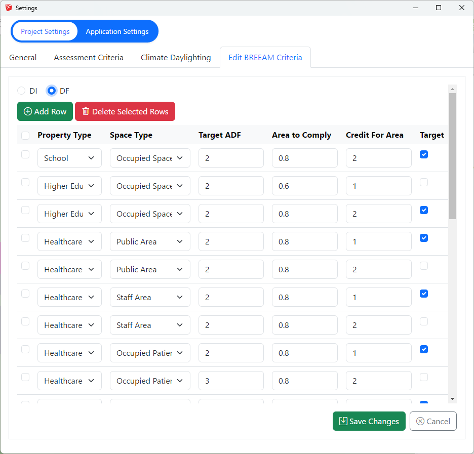
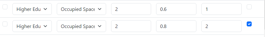
Each property and room type pair in BREEAM Regulations Table 5.1 is translated into one or two rows(based on number of credits, target lux, occupied hours) in the dialogue.
If a property, room type pair has different credits or target DF, one row is added for each credit in the table dialog.
For example, Higher education occupied space can achieve 1 credit with 60% area with 2% and 2 credits with 80% area with 2%
Two records are added to the table with the corresponding values for credit value and target DF.
The first entry for higher credit is selected for calculation.
– To Delete an existing criterion select the row on the table and press the Delete Selected Row button.
To Add a new criterion, click on the Add Row button. This will insert a new criteria row with a dummy value. Adjust these values accordingly.
– To Update an existing criterion simply change the values on the table.
The Selected column displays the criteria that are set for calculation. The DF calculation uses the
registered property and space type of a room to query its assessment criteria from the above table. If more than one records exists for this property and room type, the Selected is returned from the table. If no records exists the default “Other Building Types” and Occupied Space criterion is used.
Notes for All DF Criteria
Note 1: The output report displays criteria that has been set prior to running the calculation.
In other words the selected criteria record is saved against the room on calculation time and same criteria is queried at report time.
Note 2: Changing the Selected criteria, changes to Target DF, Target DF Min requires re-running the calculation.
“Area To Comply” and “Credit For Area To Comply” does not require rerun.
Steps to run Daylight Factor Calculation
- Prepare the model with appropriate material. For your convenience, you can use built-in MBS material such as External wall, Ground, Ceiling etc.
- The registered windows will automatically get Glass material based on their properties set during the registration time.
However the registered windows must be added to relevant group before conversion.
For more details on how to setup the model for running Daylight Factor and questions on Window Glazing Transmittance,
please refer to the topic How to prepare a model for Assigning the Materials? in Materials knowledge base section. - Open the Material dialog and assign a material for each layer. Material Library has a predefined list of most of the common materials. Yet you can define your own or customize them.
For more details on how the material dialogue works please refer to the About Material Dialog topic in Materials knowledge base section. - Set the Ray tracing Method and its options on Application Settings > Calculation tab > Ray Tracing section.
- The Sky distribution used for Daylight Factor is CIE Overcast Sky.
- Tick Convert to Radiance format or Convert to GPU format before Converting the model.
- Finally run the calculation
- Open Calculation Dialog
- Click on relevent regulation tab
- Select DF calculation and click on Add to List
- Next click on Run
Climate Based Calculations
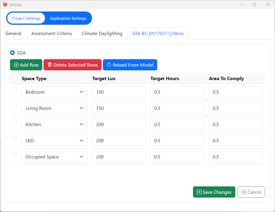
BS EN17037 Illuminance (SDA) Criteria
Illuminance Criteria
UK National Annex
The UK Annex is intended for “hard to light” dwellings.
The illuminance targets for BS EN17037 SDA can be accessed via Project Settings Climate Daylighting tab.
The target Lux is to be met for 50% of the time over 50% of the space.
Notes (Also Applies to EN17037 Criteria too)
- Daylight Hours: The hours of daylight are determined by rank-ordering (i.e. from highest to lowest) the 8760 values for diffuse horizontal illuminance and then extracting the first (i.e. the highest) 4380 hourly values. Note that the retained (i.e. highest) 4380 values may include some zero values, or that the discarded 4380 values may include some non-zero values.
This is to be expected given the nature of illuminance data in climate files and does not affect the outcome. - The relevant area of the space plane covers the entire space, and is located 0.85m above the floor.
- A perimeter area is excluded from the area of the space, because locally, illuminances are not relevant to the assessment of daylight provision, since the illuminances can be excessively high (near windows) or excessively low, next to opaque walls. A perimeter area is the area located next to the walls of the space, and should be excluded in daylight calculations.
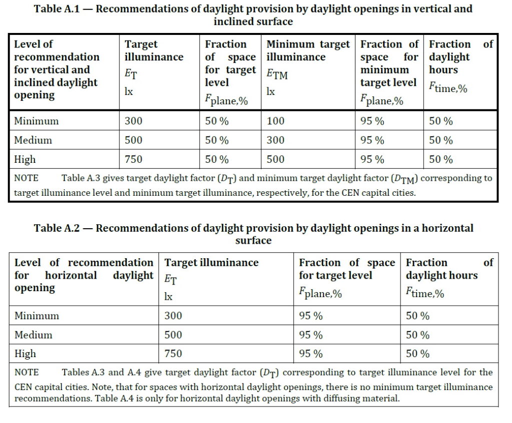
EN17037 Illuminance (SDA) Criteria
Illuminance Criteria
The illuminance targets for BS EN17037 SDA can be accessed via Project Settings Climate Daylighting tab.
For spaces with daylight openings in vertical and inclined surface, The target Lux is to be met for 50% of the time over 50% of the space. The min target Lux is to be met for 50% of the time over 95% of the space.
For spaces with daylight openings in horizontal surface, The target Lux is to be met for 50% of the time over 95% of the space. There is no minimum target lux.
BREEAM Illuminance (DI) Criteria
Terms and Definitions
Average daylight Illuminance
Daylight illuminance for all points in the space for a specific hour (e.g. 1st Jan 8 AM) is averaged. If this average is over the target lux (e.g. 300 lux) value, the hour will count towards the achieved hour for the target lux.
Minimum Daylight Illuminance
The lowest point daylight illuminance in the space at a specific hour e.g. 1st Jan 8 AM) on the working plane within a room. The minimum point daylight factor is the lowest value of the daylight factor on the working plane at a point that is not within 0.5m of a wall. If this lowest lux value is over the target lux min value (e.g. 90 lux), the hour will count towards the achieved hour for the target lux min.
Setting Weather Location and Hours
Setting up Weather data and Location
Select location for climate based calculation on Project Settings dialogue > General tab > Location section. All weather data files must be in epw format and located in below folder:
Sketchup: %appdata%/MBS Software/DaylightForSketchup/Climate Files
For new locations, the .epw file (IWEC format) can be downloaded from the energy plus website.
- Select the region then the country then the location and then select epw to download the file.
- Once downloaded copy the .epw file to the above appdata folder.
This setting is project specific and needs to be set per job.
Setting up Climate Hours
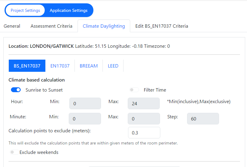
- Before running the calculation, the regulation and annual daylight hours options have to be set through Project Settings > Climate Daylighting tab.
- The test has to be run separately for each regulation. Results are saved per regulation and thus once they are calculated, corresponding reports could be outputted without a re-run.
- The recommended daylight hours for BREEAM, BS EN17037and EN17037 is Sunrise to Sunset.
- For BS EN17037 and EN17037, 50% of the hours with the highest illuminance (4380 hours) is used instead of all the hours between sunrise and sunset.
- The filter hour is inclusive for the start hour and exclusive for the end hour.
For example, if the occupancy starts at 9 AM and finishes at 5PM, the filter hour should be set to 9 to 17 (8 Hour Occupancy)
Setting Pass Criteria
Assessment Criteria are set per project in Project Settings dialogue > Climate Daylighting tab.
Select the regulation first and then Press the … button next to the regulation to open the Climate Criteria dialog for the regulation.
SDA BS EN17037 Criteria
The criteria is set according to BS EN17037 regulation. The criteria are set based on the space type.
SDA EN17037 Criteria
The criteria is set according to EN17037 Regulation. The criteria are fixed and grouped by their rating. The Selected criterion is queried and used for calculation.
BREEAM DI Criteria
All the entries on BREEAM Regulations Table 5.3 are predefined based on the BREEAM New Construction 2018 and loaded as default in Criteria table dialogue.
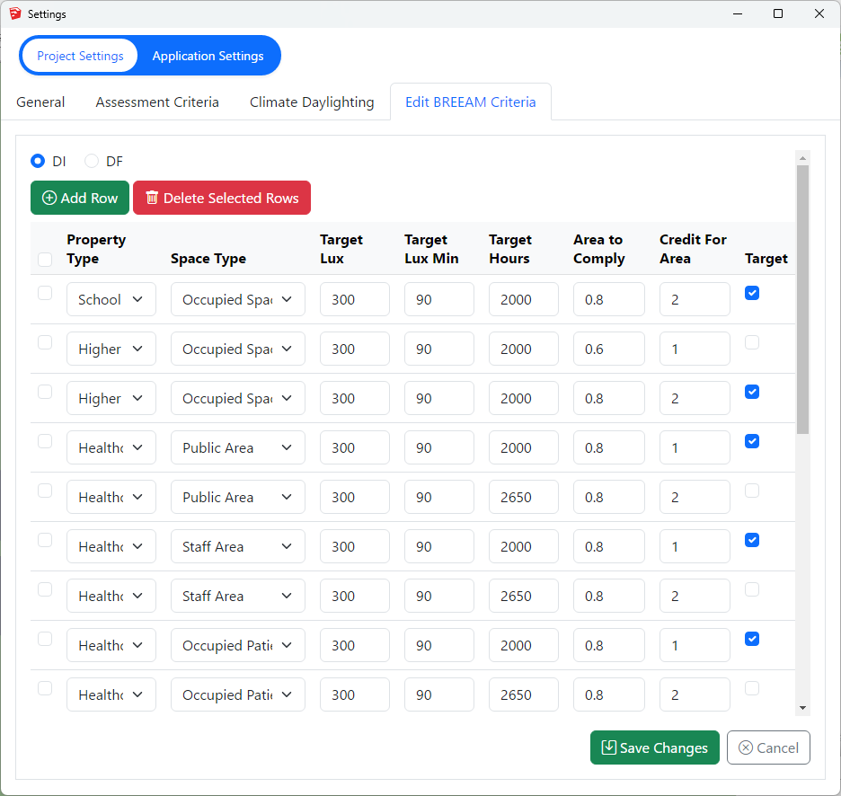
Each property and room type pair in BREEAM Regulations Table 5.3 is translated into one or two rows(based on number of credits, target lux, occupied hours) in the dialogue.
If a property, room type pair has different credits, target lux or occupied hours one row is added for each credit in the table dialogue.
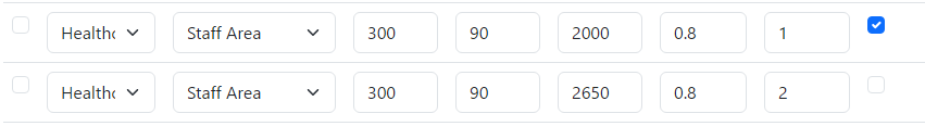
As an example, below Staff room type in Healthcare property has two entries for 1 Credit and 2 Credit with different occupied hours.
Two records are added to the table with the corresponding values for credit value, target lux and occupied hours.
The first entry for credit 1 is selected for calculation.
– To Delete an existing criterion select the row on the table and press the Delete Selected Row button.
To Add a new criterion, click on the Add Row button. This will insert a new criteria row with a dummy value. Adjust these values accordingly.
– To Update an existing criterion simply change the values on the table.
The Selected column displays the criteria that are set for calculation. The DI calculation uses the
registered property and space type of a room to query its assessment criteria from the above table. If more than
one records exists for this property and room type, the Selected is returned from the table. If no records exists
the default “Other Building Types” criterion is used.
Notes for All Climate Criteria
Note 1: The output report displays criteria that has been set prior to running the calculation.
In other words the selected criteria record is saved against the room on calculation time and same criteria is queried at report time.
Note 2: Changing the Selected criteria, changes to Target Lux, Target Lux Min, Target Hours requires re-running the calculation.
“Area To Comply” and “Credit For Area To Comply” does not require rerun.
Steps to run Climate-Based Calculation
- Prepare the model with appropriate material. For your convenience, you can use built-in MBS material such as External wall, Ground, Ceiling etc.
- The registered windows will automatically get Glass material based on their properties set during the registration time.
However the registered windows must be added to relevant group before conversion.
For more details on how to setup the model for running Daylight Factor and questions on Window Glazing Transmittance,
please refer to the topic How to prepare a model for Assigning the Materials? in Materials knowledge base section. - Open the Material dialog and assign a material for each layer. Material Library has a predefined list of most of the common materials. Yet you can define your own or customize them.
For more details on how the material dialogue works please refer to the About Material Dialog topic in Materials knowledge base section. - Set the Ray tracing Method and its options on Application Settings > Calculation tab > Ray Tracing section.
- The Sky distribution used for Daylight Factor is CIE Overcast Sky.
- Tick Convert to Radiance format or Convert to GPU format before Converting the model.
- Finally run the calculation
- Open Calculation Dialog
- Click on relevent regulation tab (BREEAM, BS EN17037 or EN17037 or LEED or EFA)
- Select SDA or DI calculation and click on Add to List
- Next click on Run
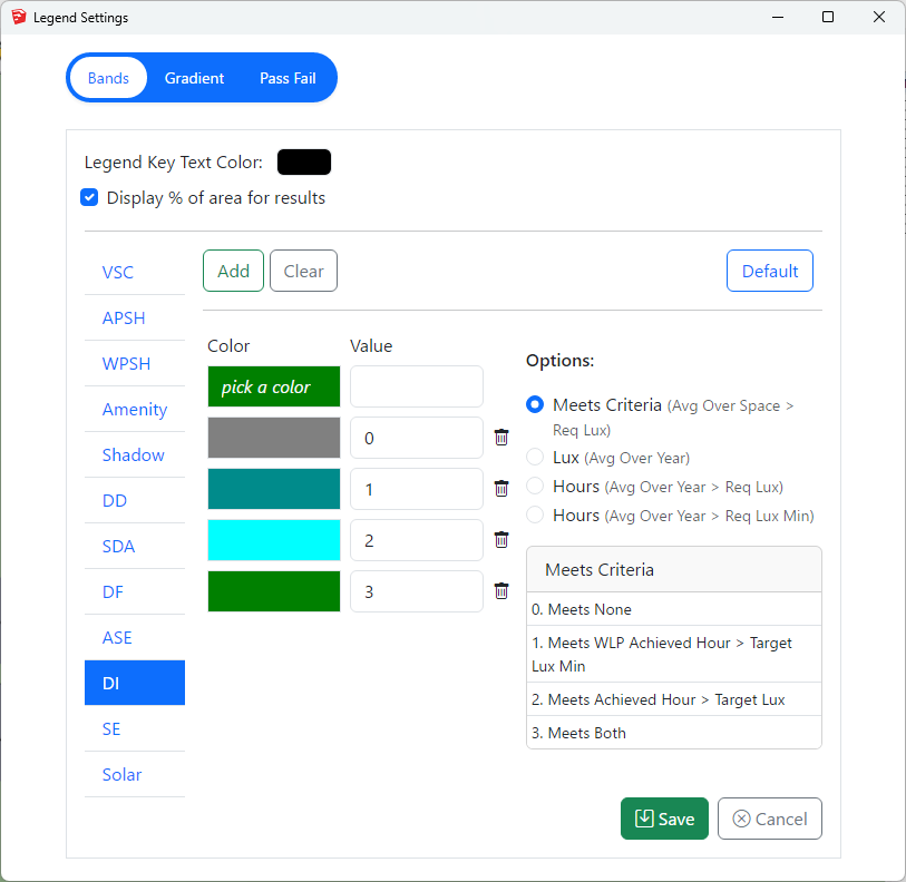
BREEAM DI Results
The DI results can be presented visually in 4 different ways.
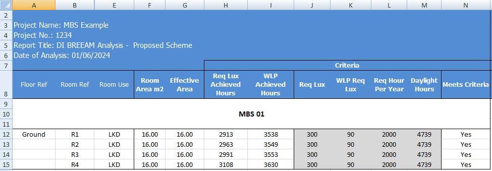
- As shown in the image, the Meets criteria option will show a single colour image for the room based on whether Achieved hour > Target Lux and/or Worst lit point achieved hour > Target Lux Min are met or not.
- Please note that the rest of the three options are alternative presentation of the result and do not show the achieved hour for target lux and target lux min as averaged over the space
- The Lux (Avg Over Year) option can be used to show the average lux achieved by each point in the room over the year.
- Hours (Over Year > Req Lux) option can be used to show the number of hours when each point in the room achieve the req lux.
- Hours (Over Year > Req Lux Min) option can be used to show the number of hours when each point in the room achieve the req lux min.
The DI Excel result contains the results for the main criteria as well as some alternative results.
As shown in the DI criteria results image,
- The Req Lux Achieved Hours column shows the total number of hours when lux value averaged over the space is at least 300 Lux.
- The WLP Achieved Hours column shows the total number of hours when the worst lit point lux value (except foe the points within 0.5m of the wall) is at least 90 Lux.
- The Meets Criteria column shows Yes, If both Req Lux Achieved Hours and WLP Achieved Hours are more than the 2000 hours (Req hour per year).
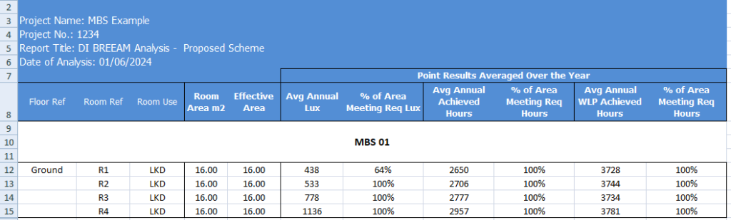
The Alternative result columns are to the right of the Meets criteria column and are added to give alternative results for each points over the year.
- The Avg Annual Lux column shows the average lux value based on the average lux achieved by all the points in the room. Each points average lux value can be shown by using the Lux (Over the year) option in Legend settings.
- The % of Area Meeting Req Lux column shows the percent of the points which have an average of at least 300 Lux.
- The Avg Annual Achieved Hours column shows the average achieved hours value based on the achieved hours with at least 300 lux achieved by all the points in the room. Each points achieved hours with at least 300 lux can be shown by using the Hours (Over Year > Req Lux) option in Legend settings.
- The % of Area Meeting Req Hours column shows the percent of the points which achieve 2000 hours with at least 300 Lux.
- The Avg Annual WLP Achieved Hours column shows the average achieved hours value based on the achieved hours with at least 90 lux achieved by all points in the room. Each points achieved hours with at least 90 lux can be shown by using the Hours (Over Year > Req Lux Min) option in Legend settings.
- The % of Area Meeting Req Hours (WLP) column shows the percent of the points which achieve 2000 hours with at least 90 Lux.
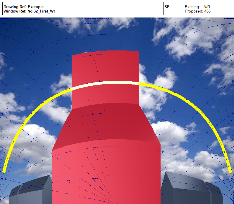
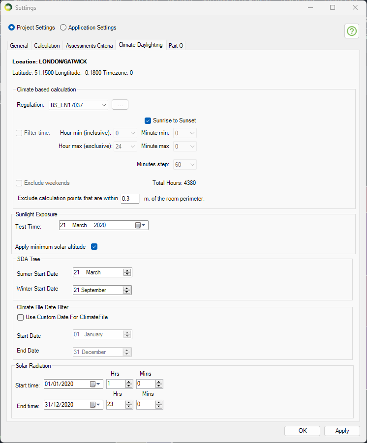
Sunlight Exposure
Minimum recommendation
This is to be checked in the reference point at the centre of the window width and at the
inner surface of the aperture (façade and/or roof). For multiple apertures in different façades it is possible to cumulate the time of sunlight availability if not occurring at the same time. The reference point is minimum 1.2 m above the floor and 0.3 m above the window sill (whichever is higher).
NOTE 1 To allow flexibility for rooms orientation the angle of window normal αwn,s = 120° measured from South and the minimum sun height γs,min are applied. Solar altitudes below those stated in Table D.1 (BS EN17037 guide) are neglected in the evaluation.
Minimum recommendation for exposure to sunlight
The minimum recommendation is that the room should receive possible sunlight for a duration higher than 1.5 hours (supposed to be cloudless) on March 21.
Table A.5 proposes three levels for exposure to sunlight.
| Recommendation | Sunlight Exposure (Hours) |
| Minimum Exposure | >= 1.5 |
| Medium Exposure | >= 3.0 |
| High Exposure | > 4.0 |
Table A.5
Run calculation
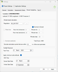
The test date can be changed on Project Settings > Climate Daylighting tab.
The default date is set for March 21.
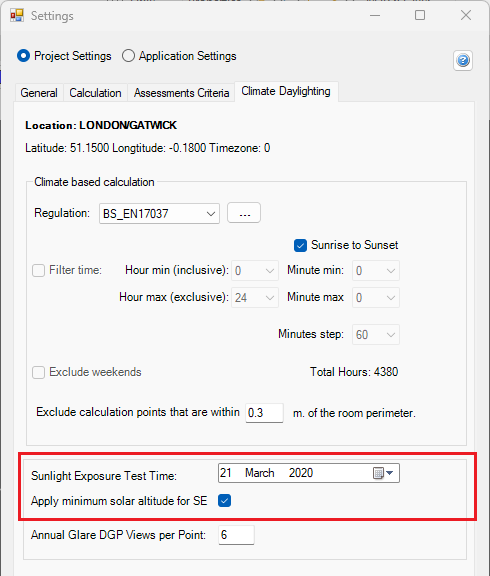
Open Run dialogue and select Sunlight Exposure to run the calculation.
SDA Calculation With Trees
In order to include Trees in the SDA annual calculation, the new Annualtree material should be used. It combines the existing TransTree material to specify Summer and Winter materials for trees. The dates for Summer and Winter trees is specified in Project Settings > Climate Daylighting. This is a special material for SDA calculation and should not be used with any other calculations.
e.g. if the Annualtree material is used with Summer Start Date 21 March and Winter Start Date 21 September then the SDA calculation is run once for the Summer date e.g. 21 March to 20 September using the Summer tree material and once for the Winter date e.g. 21 September to 20 March using the Winter tree material. The results are then combined to give an overall annual result.
Façade Analysis
Façade Calculation
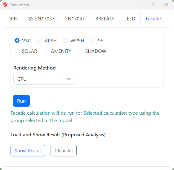
How to run facade analysis?
- Facade analysis is performed on group containing Sketchup faces.
- The facade faces must be facing out for vertical faces and up for horizontal faces.
- Select the group on the Outliner.
- Open the Calculation Dialog by clicking
 icon.
icon. - Go to Facade tab and then select the calculation.
- WPSH is run along with the APSH but the results come separately.
- Press the Run button.
- Once the analysis is complete, Select the Result group and Press Show Result.
- Press Clear All to hide all the facade results.
Façade Analysis FAQs
How to change colour of façade analysis results?
- Facade analysis results can be created on gradient or colour band mode.
- Gradient mode has 4 different colour options. The colour gradient is created for the min and max values provided for the calculation type. For example for VSC it is 0 and 27 by default.
- All options except Rainbow create 21 colours in total. Rainbow creates 25 colours in total.
- Intermediate colours are added to avoid colour contrast between values in two intervals. The breakdown of intermediate colours is as below:
- Two colour: 2 for the min and max colours and 19 interpolated colours between them.
- Three colour: 3 for the given colours and 9 interpolated colours between first and second and second and third colour.
- Rainbow colour: 7 for the given colours and 18 for the intermediate colours between them. (3 interpolated colours between each consecutive colour except the last one)
- Default colour: 11 for the given colours and 10 for the mid colour between them except the last one.
- Gradient Legend Interval
The interval for legend values is created by dividing the min and max values equally to the legend colours.
Interval values for legend colours are calculated using the formula (Max value – Min value) / (total colours in legend – 1). The last colour is for all values greater than max therefore (total colours – 1) is used.For example, The interval of values per Default legend colour for VSC legend with min of 0 and max of 27 will be calculated as below.
(27-0) / (21-1) = 1.35 - Colour Band Mode
- BRE mode
- If BRE option on Colour Band mode is ticked, VSC and APSH legends will be customised according to the BRE criteria. The legend will be created with just three colours for Pass, Nearly Pass and Fail. The colours can be changed by the users. The pass values for VSC and APSH is taken from Project settings Criteria section.For Example, for VSC calculation if the result >= 27 (or) loss < 20 % then it passes, if the result >= 26 (or) loss < 21 % (Tolerance = 1) then it is Nearly Passed, otherwise it will fail. The legend will show Pass, Nearly Pass and Fail results. If the calculation is run for neighbour scheme only one legend is created.
- There are no default values for non-gradient legend mode. Users must define the range for each calculation type before running the calculation. If non-gradient legend values are not defined for the calculation, the default gradient mode is used.Select the calculation type radio button to define the colour band values. Then click on the Color textbox to choose a colour and enter a value. The values must be in ascending order. The first value will be the minimum value and last value will be maximum value for any calculation. The ratio colour and values fields can be left empty if the calculation is only being run for Proposed scheme.
- BRE mode
Why do I get “Selection is not valid. Please Select a Group..” error despite selecting a group with valid faces?
- Horizontal faces which are facing downward are ignored by default.
- This option can be turned off from Settings –> Application Settings -> Calculation –->Façade section and Ignore Horizontal Downward faces. If such faces are needed to be analysed.
- Reverse the faces and Run the façade analysis again.
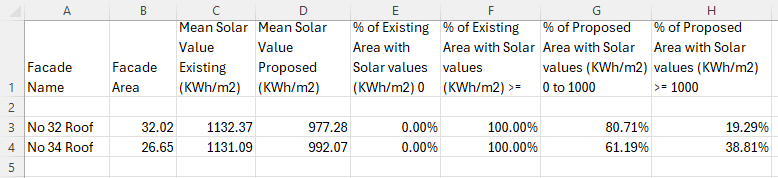
Solar Radiation
Solar Radiation
Solar Radiation can be run as a Facade calculation, the model must be converted to Radiance and thus requires Radiance to be installed on the computer.
The test date can be changed on Project Settings > Climate Daylighting tab. The default date is set for 01 Jan to 31 Dec
- This is a an annual cumulative Solar radiation calculation.
- The final output is given in KWh/m2
- The calculation is based on the epw climate file.
- The calculation includes direct contribution from the sun on cloudy condition (as per the climate file) and also includes the contribution from the atmosphere.
- A legend image and CSV report are created during the calculation.
- The CSV report includes values for all the ranges that are defined in the Legends settings. The default is set to 0 to 1000 Kwh/m2
Transient Shadow Render
Transient Shadow Analysis
FAQs
The objects come very small in the rendered image.
Make sure the Menu bar > Camera is set to Perspective.
How can I reduce the noise in the image?
Increase the Pixel Samples to above 100 to get a sharper image.
The noise is inversely proportional to square root of this number: four times more samples are required to decrease the error by half.
How can I change the brightness of the image?
Open the Render dialogue and press the “![]() ” icon to open the settings.
” icon to open the settings.
Set the exposure to a lower value. If the values was already set to 1, try a fraction e.g. 0.6
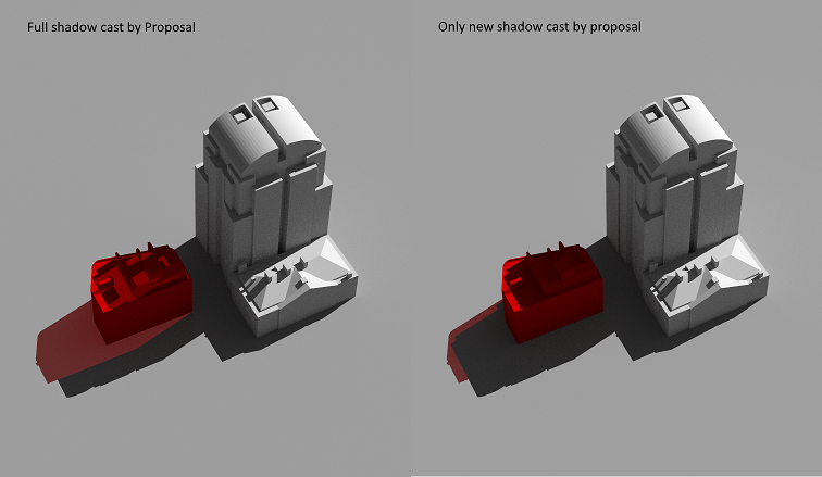
What is New Shadow Only option in render dialogue?
Tick New Shadow Only option to exclude part of the coloured shadow that already is rendered under the existing scenario.
Do I need to have a ground surface in the model for Transient Shadow analysis?
No. The software will insert a virtual ground just below the bounding box of the model.
You can remove the virtual ground by unticking the option on Render dialogue > “![]() ” > “Remove virtual ground”
” > “Remove virtual ground”